

BOSCH REXROTH
R911170754
$194.15 USD
- BOSCH REXROTH
- Material:R911170754
- Model:R-IBIL24DO2-2A-PAC
Quantity in stock: 11
The Bosch Rexroth R-IB IL 24 DO 2-2A-PAC (R911170754) is a highly efficient digital output module designed for seamless integration within an Inline station. This module excels in outputting digital signals, ensuring reliable and accurate control for various applications. The R-IB IL 24 DO 2-2A-PAC is engineered to facilitate smooth communication within automated systems, making it an essential component in sophisticated control environments. With its robust design, the module provides a secure solution for managing digital outputs, which is crucial for maintaining the integrity and performance of complex machinery. Its compatibility with the Inline station series allows it to be easily incorporated into existing systems without the need for extensive modifications. The capability of this module to handle digital signal outputs with precision makes it a valuable asset in scenarios that demand exacting control and responsiveness. In summary, the Bosch Rexroth R-IB IL 24 DO 2-2A-PAC is specifically tailored to deliver high-quality digital signal outputting within an Inline station setup. Its precise engineering and compatibility features ensure that it meets the demanding requirements of various applications where accurate digital control is paramount.
Inline connector
The modular, compact equipment configuration of the I/O systems from Rexroth offers you maximum flexibility for the cost-effective implementation of your individual machine concepts. The I/O modules have robust design and mechanics, are easy to use, have a quick reaction time and are quick to install – both in the control cabinet and in the field. Open communication standards allow you perfect integration of the I/O modules with maximum availability.
Unpacked Weight: 0.087 kg
This module is designed for use within an Inline station. It is used to output digital signals.
| Data Sheet | Download Data Sheet |
| 3D CAD | Download 3D CAD |
| Manual | Download Manual |
| Air pressure (operation) | 70-106 kPa (up to 3,000 m above sea level) |
| Total current | 4 |
| Air pressure (storage / transport) | 70-106 kPa (up to 3,000 m above sea level) |
| Width | 12.2 |
| Productgroup ID | 4,6 |
| Overload-/ short circuit protection in the segment circuit | Electronic |
| Height | 120 |
| International protection code | IP20 |
| Permissible air humidity (storage) | 10-95 |
| Permissible air humidity (transport) | 10-95 |
| Number of channels | 2 |
| Connection type | Zugfederanschluss |
| Connection techniques | 2-, 3- und 4-Leitertechnik |
| Depth | 71.5 |
| Weight | 0.087 |
| Ambient temperature (during operation) | -25-55 |
| Ambient temperature (storage and transport) | -25-85 |
| Conductor cross-section | Rigid: 0.08-0.5 mm²,Flexible: 0.08-0.5 mm²,AWG: 28 ... 16 |
General data
|
Type |
R-IB IL 24 DO 2-2A-PAC | |
|
Weight 1) |
g |
61 |
|
Operating mode |
Process data operation with 2 bits | |
|
Actuator connection type |
2-, 3- and 4-wire technology | |
|
Ambient temperature (operation) |
-25 °C ... +55 °C | |
|
Ambient temperature (storage/transport) |
-25 °C ... +85 °C | |
|
Permissible relative humidity (operation) |
10 % ... 95 % acc. to DIN EN 61131-2 | |
|
Permissible relative humidity (storage/transport) |
10 % ... 95 % acc. to DIN EN 61131-2 | |
|
Air pressure (operation) |
70 kPa ... 106 kPa (up to 3000 m above sea level) | |
|
Air pressure (storage/transport) |
70 kPa ... 106 kPa (up to 3000 m above sea level) | |
|
Protection type |
IP20, IEC 60529 | |
|
Protection class |
III, EN 61131-2, IEC 61131-2 | |
| 1) | Including plug |
Connection data
|
Type |
R-IB IL 24 DO 2-2A-PAC | |
|
Designation |
Inline connection plug | |
|
Connection type |
Tension spring modules | |
|
Conductor cross-section solid/flexible/AWG |
0.08 mm² ... 1.5 mm² 0.08 mm² ... 1.5 mm² 28 ... 16 |
|
Interface local bus
|
Type |
R-IB IL 24 DO 2-2A-PAC | |
|
Connection type |
Data ranking | |
|
Transmission speed |
kBit/s |
500 |
Supply of module electronics and peripherals via bus coupler/power feed module
|
Type |
R-IB IL 24 DO 2-2A-PAC | |
|
Connectivity technology |
Via potential jumpers | |
Inline potentials/performance balance
|
Type |
R-IB IL 24 DO 2-2A-PAC | |
|
Logic voltage |
V DC |
7.5 |
|
Maximum current consumption from UL |
mA |
35 |
|
Maximum power consumption from UL |
W |
0.27 |
|
Segment supply voltage US |
V DC |
24 |
|
Nominal current consumption from US |
≤ 4 A (2 x 2 A) | |
Digital outputs
|
Type |
R-IB IL 24 DO 2-2A-PAC | |||
|
Number of digital outputs |
2 | |||
|
Nominal output voltage UOut |
V DC |
24 | ||
|
Differential voltage at INenn |
V |
≤ 1 | ||
|
Nominal current INenn each channel |
A |
2 | ||
|
Nominal current tolerance |
% |
+ 10 | ||
|
Total current |
A |
4 | ||
|
Nominal load |
Ohmic |
12 Ω |
W |
48 |
|
Lamps |
W |
48 | ||
|
Inductance |
1.2 H; 50 Ω |
VA |
48 | |
|
Signal delay upon turning on of a |
Ohmic nominal load |
µs |
200 | |
|
Lamp nominal load 1) |
ms |
200 | ||
|
Inductive nominal load |
1.2 H; 12 Ω |
ms |
250 | |
|
Signal delay upon deactivating a |
Ohmic nominal load |
µs |
≈ 200 | |
|
Lamp nominal load |
µs |
200 | ||
|
Inductive nominal load |
1.2 H; 12 Ω |
ms |
250 | |
|
Maximum switching frequency for a |
Ohmic nominal load |
Hz |
300 | |
|
Lamp nominal load |
Hz |
300 | ||
|
Inductive nominal load |
1.2 H; 48 Ω |
Hz |
0.5 | |
|
Behavior for overload |
Automatic restart | |||
|
Behavior for inductive overload |
Output can be destroyed | |||
|
Reverse voltage protection from short pulses |
Reverse voltage protection | |||
|
Resistance to permanently generated reverse voltage |
A |
≤ 2 | ||
|
Validity of the output data after switching on the 24 V supply voltage (power up) |
Typ. 5 ms | |||
|
Behavior when the voltage is deactivated (power down) |
The output follows the power supply without delay | |||
|
Limited inductive cut-off voltage |
V |
≈ - 0.7 | ||
|
Maximum inductive switch-off power/channel |
Max. 1500 W (pulse 8/20 μs ) | |||
|
Type of external protection circuit |
Free-wheel diode per channel | |||
|
Overload/short-circuit protection in the segment circuit |
Electronic | |||
|
Overvoltage/reverse polarity protection supply voltage |
Protective elements of the feed module | |||
| 1) | For switching frequencies up to 8 Hz; above this frequency, the lamp load responds like an ohmic load |
|
Power dissipation |
|
|
Formula for calculating the power dissipation in the electronics |
|

|
|
|
where: |
|
|
PEL |
Total power dissipation in the module |
|
n |
Number of set outputs (n = 1 to 2) |
|
i |
Running index |
|
ILi |
Load current of output i |
|
Power dissipation of housing dependent on the ambient temperature |
|

|
|

|
|
|
where: |
|
|
PGEH |
Admissible power dissipation of housing |
|
TU |
Ambient temperature |
Restriction of simultaneity, derating
|
Ambient temperature TA |
55 °C | 40 °C | |
|
Maximum load current at 100 % simultaneity |
A |
1 | 2 |
|
Maximum load current at 50 % simultaneity |
A |
2 | 2 |
|
At an ambient temperature of 55 °C, a load current of 1 A per channel is allowed at 100 % simultaneity. If you are only operating one channel (50 % simultaneity), a load current of 2 A can be inferred. If you are operating both channels, you must determine the permissible working point based on the formulas specified above. For an example of this, see the application description "Configuration and installation of the Rexroth Inline product family". |
|||
Electrical isolation/insulation of the voltage ranges
|
Type |
R-IB IL 24 DO 2-2A-PAC | |
|
Common potentials |
||
|
24 V main voltage UM, 24 V segment voltage US and GND are on the same potential. FE represents a separate potential area. |
||
|
Separate potentials in the system of bus coupler/feed module and I/O module |
||
|
Test distance |
Test voltage | |
|
5 V supply incoming remote bus/7.5 V supply (bus logic) |
500 V AC, 50 Hz, 1 min. | |
|
5 V supply to further remote bus/7.5 V supply (bus logic) |
500 V AC, 50 Hz, 1 min. | |
|
7.5 V supply (bus logic)/24 V supply (peripherals) |
500 V AC, 50 Hz, 1 min. | |
|
24 V supply (peripherals)/function earth |
500 V AC, 50 Hz, 1 min. | |
Error messages to the higher-level control or computer system
|
Type |
R-IB IL 24 DO 2-2A-PAC | |
|
Error message |
Short-circuit/overload of an output Under or over the operating voltage |
|
|
Approvals |
|
The current approvals can be found at www.boschrexroth.com. |
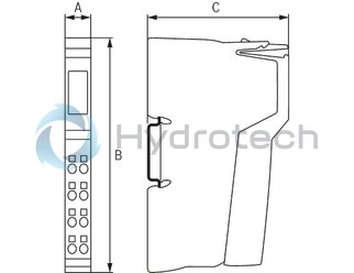
Dimensions
|
Type |
R-IB IL 24 DO 2-2A-PAC | |
|
A |
mm |
12.2 |
|
B |
mm |
120 |
|
C |
mm |
71.5 |
|
Note on dimensions |
The depth applies when using a support rail TH 35-7.5 (acc. to EN 60715). | |