

BOSCH REXROTH
R911170710
$152.26 USD
- BOSCH REXROTH
- Material:R911170710
- Model:R-IB IL 24 SEG/F-D-PAC
Quantity in stock: 0
The Bosch Rexroth R-IB IL 24 SEG/F-D-PAC (R911170710) is a specialized module crafted for integration within an Inline station, serving the purpose of constructing a fuse-protected subcircuit segment within a larger main circuit framework. This particular module is not designed to provide power supply and, as such, does not incorporate features for reverse polarity or overvoltage protection. It is equipped with an intuitive LED diagnostic system that assists users in monitoring operational status. The module utilizes two input data bits to relay critical information regarding supply voltage presence and the condition of the fuse, ensuring reliable performance and safety in application. The R-IB IL 24 SEG/F-D-PAC comes complete with necessary accessories including a connection plug and a labeling field, which simplifies installation and maintenance processes. Its design specifically caters to systems requiring segment modules operating at VDC with fuse protection and diagnostic capabilities. The inclusion of these features makes this module an essential component for creating segmented circuits that maintain high levels of safety and functionality within industrial automation setups. Bosch Rexroth's attention to detail in providing comprehensive solutions is evident in the thoughtful engineering of the R-IB IL 24 SEG/F-D-PAC module.
Inline connector
The modular, compact equipment configuration of the I/O systems from Rexroth offers you maximum flexibility for the cost-effective implementation of your individual machine concepts. The I/O modules have robust design and mechanics, are easy to use, have a quick reaction time and are quick to install – both in the control cabinet and in the field. Open communication standards allow you perfect integration of the I/O modules with maximum availability.
Unpacked Weight: 0.087 kg
This module is designed for use within an Inline station. It can be used to build a fuse-protected sub-circuit (segment circuit) within a main circuit. The module cannot be used to supply power, so it does not come with any reverse polarity or overvoltage protection. This module has an LED for diagnostics and uses two input data bits, which are used to indicate the presence of the supply voltage and the status of the fuse.
| Data Sheet | Download Data Sheet |
| 3D CAD | Download 3D CAD |
| Manual | Download Manual |
| Air pressure (operation) | 70-106 kPa (up to 3,000 m above sea level) |
| Air pressure (storage / transport) | 70-106 kPa (up to 3,000 m above sea level) |
| Rated value; 24V periphery (main circuit UM) | The main voltage UM is fed in the bus coupler or in a power terminal. The segment voltage US is automatically provided at this segment terminal and secured by means of the internal fuse. At the segment terminal, there are no connections for the feed-in of supply voltage. The terminal points are exclusively provided for measurement purposes. |
| Width | 12.2 |
| Productgroup ID | 4,6 |
| Height | 120 |
| Maximum current | 6.3 |
| International protection code | IP20 |
| Permissible air humidity (storage) | 10-95 |
| Permissible air humidity (transport) | 10-95 |
| Connection type | Zugfederanschluss |
| Depth | 71.5 |
| Weight | 0.087 |
| Ambient temperature (during operation) | -25-55 |
| Ambient temperature (storage and transport) | -25-85 |
| Conductor cross-section | Rigid: 0.2-1.5 mm²,Flexible: 0.2-1.5 mm²,AWG: 24 ... 16 |
General data
|
Type |
R-IB IL 24 SEG/F-D-PAC | |
|
Weight 1) |
g |
59 |
|
Operating mode |
Process data operation with 2 bits | |
|
Ambient temperature (operation) |
-25 °C ... +55 °C | |
|
Ambient temperature (storage/transport) |
-25 °C ... +85 °C | |
|
Permissible relative humidity (operation) |
10 % ... 95 %, EN 61131-2 | |
|
Permissible relative humidity (storage/transport) |
10 % ... 95 %, EN 61131-2 | |
|
Air pressure (operation) |
70 kPa ... 106 kPa (up to 3000 m above sea level) | |
|
Air pressure (storage/transport) |
70 kPa ... 106 kPa (up to 3000 m above sea level) | |
|
Protection type |
IP20, IEC 60529 | |
|
Protection class |
III, VDE 0106, IEC 60536 | |
| 1) | Including plug |
Connection data
|
Type |
R-IB IL 24 SEG/F-D-PAC | |
|
Designation |
Inline connection plug | |
|
Connection type |
Tension spring modules | |
|
Conductor cross-section solid/flexible/AWG |
0.2 mm² ... 1.5 mm² 0.2 mm² ... 1.5 mm² 24 ... 16 |
|
Interface local bus
|
Type |
R-IB IL 24 SEG/F-D-PAC | |
|
Connection type |
Data ranking | |
|
Transmission speed |
kBit/s |
500 |
Inline potentials/performance balance
|
Type |
R-IB IL 24 SEG/F-D-PAC | |
|
Supply to the main circuit UM |
V DC |
24 |
|
Logic voltage UL |
V DC |
7.5 |
|
Maximum current consumption from UL |
mA |
25 |
|
Maximum power consumption from UL |
W |
0.19 |
|
Nominal current consumption from UM 1) |
A |
4 |
| 1) | Rated value |
Supply of module electronics and peripherals via bus coupler/power feed module
|
Type |
R-IB IL 24 SEG/F-D-PAC | |
|
Connectivity technology |
Potential jumpers | |
|
24 V peripheral supply (UM, US) |
|
The main voltage UM is fed in the bus coupler or in a feed module. The segment voltage US is provided automatically at this segment module and protected via the internal fuse. There are no connections for the feed of a supply voltage at the segment module. The module points are only intended for measuring purposes. |
Permissible total current in the potential jumpers of the main and segment circuits
|
Type |
R-IB IL 24 SEG/F-D-PAC | |
|
Permissible total current in the potential jumpers |
A |
6.3 |
|
Nominal module current |
A |
4 |
|
Tolerance |
% |
+ 10 |
Derating of the load current in the segment circuit
|
Type |
R-IB IL 24 SEG/F-D-PAC | |
|
Derating |
No derating |
Protective devices
|
Type |
R-IB IL 24 SEG/F-D-PAC | |
|
Overload/short-circuit protection in the segment circuit |
Safety fuse 5 x 20 mm with 6.3 A time-lag (maximum value of fuse 8 A. For fuses with a value of greater than 2 A, only use slow fuses!) | |
|
Reverse polarity protection |
Protection components in the feed module or in the bus coupler | |
|
Overvoltage protection |
Protection components in the feed module or in the bus coupler | |
Electrical isolation/insulation of the voltage ranges
|
Type |
R-IB IL 24 SEG/F-D-PAC | |
|
Common potentials |
||
|
24 V main voltage UM, 24 V segment voltage US and GND are on the same potential. FE represents a separate potential area. |
||
|
Separate potentials in the system of bus coupler/feed module and I/O module |
||
|
Test distance |
Test voltage | |
|
5 V supply incoming remote bus/7.5 V supply (bus logic) |
500 V AC, 50 Hz, 1 min. | |
|
5 V supply to further remote bus/7.5 V supply (bus logic) |
500 V AC, 50 Hz, 1 min. | |
|
7.5 V supply (bus logic)/24 V supply (peripherals) |
500 V AC, 50 Hz, 1 min. | |
|
24 V supply (peripherals)/function earth |
500 V AC, 50 Hz, 1 min. | |
Error messages to the higher-level control or computer system
|
Type |
R-IB IL 24 SEG/F-D-PAC | |
|
Error message |
Peripheral message for triggered or missing fuse Peripheral message for missing supply voltage UM |
|
|
Approvals |
|
The current approvals can be found at www.boschrexroth.com. |
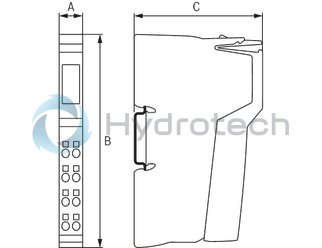
Dimensions
|
Type |
R-IB IL 24 SEG/F-D-PAC | |
|
A |
mm |
12.2 |
|
B |
mm |
120 |
|
C |
mm |
71.5 |
|
Note on dimensions |
The depth applies when using a support rail TH 35-7.5 (acc. to EN 60715). | |