

BOSCH REXROTH
R911170446
$392.23 USD
- BOSCH REXROTH
- Material:R911170446
- Model:R-IB IL 24 PWR IN/R-PAC
Quantity in stock: 0
The Bosch Rexroth R-IB IL 24 PWR IN/R-PAC (R911170446) is a state-of-the-art power feed terminal designed to integrate seamlessly within an Inline station. This module is particularly useful when the maximum ampacity of the potential shunter UL has been reached, allowing for the reapplication of logic voltage. By applying a 24 V DC voltage at the terminal, it generates the necessary logic voltage UL and also provides supply voltage for analog terminals UANA. Furthermore, this versatile terminal facilitates the feeding of both the principal 24 V DC voltage UM and the segment voltage US, ensuring that your system maintains consistent power distribution across all components. It comes as a complete package with accessories including a connection plug and labeling field, which simplifies installation and maintenance while enhancing organization within your electrical setup. The R-IB IL 24 PWR IN/R-PAC terminal is designed without an internal fuse, signifying that it should be used in conjunction with proper external circuit protection to safeguard against potential electrical faults. Its robust design and reliable performance make it an essential component for managing power within complex automation systems. Whether you're looking to expand your system's capabilities or ensure stable operation, this Bosch Rexroth power feed terminal is engineered to meet high standards of efficiency and reliability.
Inline connector
The modular, compact equipment configuration of the I/O systems from Rexroth offers you maximum flexibility for the cost-effective implementation of your individual machine concepts. The I/O modules have robust design and mechanics, are easy to use, have a quick reaction time and are quick to install – both in the control cabinet and in the field. Open communication standards allow you perfect integration of the I/O modules with maximum availability.
Unpacked Weight: 0.225 kg
This terminal is designed for use within an Inline station. If the maximum ampacity of the potential shunter UL has been reached, then this terminal can be used to feed the logic voltage again. To do so, a 24 V DC voltage (U24V) is applied at the terminal; this voltage generates the logic voltage (UL) and the supply voltage for the analog terminals (UANA). This terminal also enables the 24 V DC principal voltage (UM) and the 24 V DC segment voltage (US) to be fed.
| Data Sheet | Download Data Sheet |
| 3D CAD | Download 3D CAD |
| Manual | Download Manual |
| Air pressure (operation) | 70-106 kPa (up to 3,000 m above sea level) |
| Rated value; 24V periphery (main circuit UM) | 24 V DC |
| Width | 48.8 |
| Productgroup ID | 4,6 |
| Height | 120 |
| Maximum current | 8 |
| International protection code | IP20 |
| Permissible air humidity (storage) | 10-95 |
| Permissible air humidity (transport) | 10-95 |
| Connection type | Zugfederanschluss |
| Depth | 71.5 |
| Weight | 0.225 |
| Ambient temperature (during operation) | -25-55 |
| Ambient temperature (storage and transport) | -25-85 |
| Conductor cross-section | Rigid: 0.2-1.5 mm²,Flexible: 0.2-1.5 mm²,AWG: 24 ... 16 |
General data
|
Type |
R-IB IL 24 PWR IN/R-PAC | |
|
Weight 1) |
g |
192 |
|
Ambient temperature (operation) |
-25 °C ... +55 °C | |
|
Ambient temperature (storage/transport) |
-25 °C ... +85 °C | |
|
Permissible relative humidity (operation) |
10 % ... 95 %, EN 61131-2 | |
|
Permissible relative humidity (storage/transport) |
10 % ... 95 %, EN 61131-2 | |
|
Air pressure (operation) |
70 kPa ... 106 kPa (up to 3000 m above sea level) | |
|
Air pressure (storage/transport) |
70 kPa ... 106 kPa (up to 3000 m above sea level) | |
|
Protection type |
IP20, IEC 60529 | |
|
Protection class |
III, VDE 0106, IEC 60536 | |
| 1) | Including plug |
Connection data
|
Type |
R-IB IL 24 PWR IN/R-PAC | |
|
Designation |
Inline connection plug | |
|
Connection type |
Tension spring modules | |
|
Conductor cross-section solid/flexible/AWG |
0.2 mm² ... 1.5 mm² 0.2 mm² ... 1.5 mm² 24 ... 16 |
|
Interface local bus
|
Type |
R-IB IL 24 PWR IN/R-PAC | |
|
Connection type |
Data ranking | |
Common data for 24 V feeds
|
Type |
R-IB IL 24 PWR IN/R-PAC | |
|
Rated value |
V DC |
24 |
|
Tolerance |
-15 %/+20 % acc. to EN 61131-2 | |
|
Ripple |
% |
± 5 |
|
Supply voltage range |
19.2 V ... 30 V | |
24 V main power feed/24 V segment power feed
|
Type |
R-IB IL 24 PWR IN/R-PAC | ||
|
Connection |
Via power supply plug | ||
|
Connectivity technology |
Tension spring modules | ||
|
Permissible cable length 1) |
m |
≤ 30 | |
|
Continuation |
Via potential jumpers | ||
|
Current-carrying capacity |
A |
≤ 8 | |
|
Protective devices |
Overvoltage |
Yes; input protection diodes are destroyed by permanent overload. Pulse loads up to 1500 W are short-circuited by the input protection diode. | |
|
Reverse polarity |
Yes; parallel polarity protection diodes; in the event of a fault, the high current through the diodes melts the upstream safety fuse. | ||
| 1) | Cable route is not permissible via open spaces |
24 V power feed U24V for generating UL and UANA
|
Type |
R-IB IL 24 PWR IN/R-PAC | ||
|
Connection |
Via power supply plug | ||
|
Connectivity technology |
Tension spring modules | ||
|
Permissible cable length 1) |
m |
≤ 30 | |
|
Typical current consumption |
A |
0.012 | |
|
Maximum current consumption 2) |
A |
1.25 | |
|
Protective devices |
Overvoltage |
Yes; input protection diodes are destroyed by permanent overload. Pulse loads up to 1500 W are short-circuited by the input protection diode. | |
|
Reverse polarity |
Yes; serial diode in the feed path of the mains power supply; in the event of a fault, only low current flows and does not trip a fuse in the external power supply. | ||
| 1) | Cable route is not permissible via open spaces |
| 2) | Comprising:0.75 A for logic supply0.5 A for analog voltage supply |
Module power supply
|
Type |
R-IB IL 24 PWR IN/R-PAC | ||
|
Logic power supply UL (Potential jumper) |
Rated value |
V DC |
7.5 |
|
Tolerance |
% |
± 5 | |
|
Ripple |
% |
± 1.5 | |
|
Maximum output current |
A |
≤ 2 | |
|
Electrical short-circuit protection |
Electronic | ||
|
Analog power supply UANA (Potential jumper) |
Rated value |
V DC |
24 |
|
Maximum output current |
A |
0.5 | |
|
Electrical short-circuit protection |
Electronic | ||
Power dissipation
|
Type |
R-IB IL 24 PWR IN/R-PAC | |
|
Power dissipation (device) |
≤ 2.55 W | |
|
Electrical isolation/insulation of the voltage ranges |
||
|
When supplying the 24 V feed to generate UL and UANA separate from the 24 V main supply/24 V segment supply |
Common potentials |
Main and segment supply are galvanically on the same potential. Their shared ground is led to the participants as ground potential GND, starting from the line skip module and via the potential jumper. |
|
Separated potentials |
The 24 V feed to generate UL and UANA is separated spatially from the main and segment supply and thus electrically isolated. |
|
|
When supplying the 24 V feed to generate UL and UANA by bridging the 24 V main supply/24 V segment supply |
Common potentials |
Main supply, segment supply, 24 V analog supply and 7.5 V logic supply are galvanically on the same potential. Their shared ground is led separately to the participants as ground potential "Logic GND" (UL-) for the logic and analog supply and as ground potential GND for the feed and segment levels, starting from the line skip module and via the potential jumper. |
|
Separated potentials |
None |
|
Electrical isolation/insulation of the voltage ranges
|
Type |
R-IB IL 24 PWR IN/R-PAC | |
|
Test distance |
Test voltage | |
|
7.5 V-logic, 24 V analog supply/function earth |
500 V AC, 50 Hz, 1 min. | |
|
7.5 V logic, 24 V analog supply/24 V main, 24 V segment supply |
500 V AC, 50 Hz, 1 min. | |
|
24 V main, 24 V segment supply/function earth |
500 V AC, 50 Hz, 1 min. | |
Error messages to the higher-level control or computer system
|
Type |
R-IB IL 24 PWR IN/R-PAC | |
|
Error message |
None | |
|
Approvals |
|
The current approvals can be found at www.boschrexroth.com. |
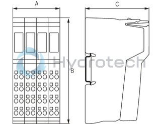
Dimensions
|
Type |
R-IB IL 24 PWR IN/R-PAC | |
|
A |
mm |
48.8 |
|
B |
mm |
120 |
|
C |
mm |
71.5 |
|
Note on dimensions |
The depth applies when using a support rail TH 35-7.5 (acc. to EN 60715). | |
|
Special requirements to be met by the voltage supply |
|
When feeding the supply voltage U24V separate from the supply voltages UM/US these are galvanically isolated from each other. This is only possible using two separate power packs. |
|
Response in the event of voltage dips and interruptions |
|
The voltages (principal and segment voltage) passed on by the feed module to the potential jumpers follow the fed supply voltages undelayed. |
|
Special requirements to be met by the voltage supply |
|
When feeding the supply voltages UM/US separate from the supply voltage U24V these are galvanically isolated from each other. This is only possible using two separate power packs. |