

BOSCH REXROTH
R911170432
$1,486.55 USD
- BOSCH REXROTH
- Material:R911170432
- Model:R-IB IL SGI 2/F-PAC
Quantity in stock: 0
The Bosch Rexroth R-IB IL SGI 2/F-PAC (R911170432) is an advanced inline analog strain gauge input module, designed for high-speed, precise data acquisition from various sensors based on strain gauge technology. This module is specifically engineered to integrate seamlessly within an Inline station setup, providing a robust solution for connecting load cells, force transducers, melt pressure transducers, and other similar devices. It supports both 3-wire and 4-wire connection technologies to accommodate different types of strain gauges. With its capability to measure the output signals of the connected strain gauges in each bus cycle, the R-IB IL SGI 2/F-PAC ensures that data is consistently updated and synchronized with the process data bus. This feature makes it particularly suitable for control applications that require a high degree of speed and accuracy. The module's focus on synchronous process data updates positions it as a reliable component in dynamic measurement systems where timely and precise data collection is critical. The R-IB IL SGI 2/F-PAC module comes complete with all necessary accessories for installation and operation, including a connection plug and labeling field which facilitate easy setup and integration into existing systems. Its design emphasizes both functionality and user-friendliness, ensuring that system integrators can quickly implement this module into their applications without extensive downtime or complex configurations. Whether used in manufacturing processes, automated testing setups or any other scenario demanding fast and accurate strain measurements, this Bosch Rexroth input module stands out as a high-performance solution in the field of industrial automation.
Inline connector
The modular, compact equipment configuration of the I/O systems from Rexroth offers you maximum flexibility for the cost-effective implementation of your individual machine concepts. The I/O modules have robust design and mechanics, are easy to use, have a quick reaction time and are quick to install – both in the control cabinet and in the field. Open communication standards allow you perfect integration of the I/O modules with maximum availability.
Unpacked Weight: 0.237 kg
This module is designed for use within an Inline station. This module provides you with a fast, two-channel input module for connecting load cells, force transducers, melt pressure transducers, and similar, and is implemented on the basis of strain gauges (DMS). The strain gauges can be connected both in 6-wire and in 4-wire technology. The output signals of the strain gauges are measured in each bus cycle and updated in the process data (bus-synchronous process data update). The module is suitable for control applications with greater demands on the speed.
| Manual | Download Manual |
| Air pressure (operation) | 70-106 kPa (up to 3,000 m above sea level) |
| Width | 48.8 |
| Productgroup ID | 4,6 |
| Height | 136.8 |
| International protection code | IP20 |
| Permissible air humidity (storage) | 10-95 |
| Permissible air humidity (transport) | 10-95 |
| Voltage input signal | 2, konfigurierbar durch Wahl des Kennwertes und der Versorgung der Brücke |
| Number of channels | 4 |
| Current input signal | 2, konfigurierbar durch Wahl des Kennwertes und der Versorgung der Brücke |
| Connection type | Zugfederanschluss |
| Connection techniques | 4-, 6-Leiter-Anschlusstechnik |
| Depth | 72 |
| Weight | 0.237 |
| Ambient temperature (during operation) | -25-55 |
| Ambient temperature (storage and transport) | -25-85 |
| Conductor cross-section | Rigid: 0.08-0.5 mm²,Flexible: 0.08-0.5 mm²,AWG: 28 ... 16 |
General data
|
Type |
R-IB IL SGI 2/F-PAC | |
|
Weight 1) |
g |
190 |
|
Operating mode |
Process data operation with 3 words/1 word PCP | |
|
Strain gauge connection type |
4-, 6-wire connection | |
|
Ambient temperature (operation) |
-25 °C ... +55 °C | |
|
Ambient temperature (storage/transport) |
-25 °C ... +85 °C | |
|
Permissible relative humidity (operation) |
10 % ... 95 % acc. to DIN EN 61131-2 | |
|
Permissible relative humidity (storage/transport) |
10 % ... 95 % acc. to DIN EN 61131-2 | |
|
Air pressure (operation) |
70 kPa ... 106 kPa (up to 3000 m above sea level) | |
|
Air pressure (storage/transport) |
70 kPa ... 106 kPa (up to 3000 m above sea level) | |
|
Protection type |
IP20, IEC 60529 | |
|
Protection class |
III, VDE 0106, IEC 60536 | |
| 1) | Including plug |
Connection data
|
Type |
R-IB IL SGI 2/F-PAC | |
|
Designation |
Inline connection plug | |
|
Connection type |
Tension spring modules | |
|
Conductor cross-section solid/flexible/AWG |
0.08 mm² ... 1.5 mm² 0.08 mm² ... 1.5 mm² 28 ... 16 |
|
Interface local bus
|
Type |
R-IB IL SGI 2/F-PAC | |
|
Connection type |
Data ranking | |
|
Transmission speed |
kBit/s |
500 |
Inline potentials/performance balance
|
Type |
R-IB IL SGI 2/F-PAC | ||
|
Logic voltage UL |
V DC |
7.5 | |
|
Typical current consumption from UL |
mA |
75 | |
|
Peripheral supply voltage UANA |
V DC |
24 | |
|
Typical current consumption from UANA |
Without DMS |
mA |
8 |
|
With maximum load 60 Ω at UV = 5 V |
mA |
32 | |
|
Typical power consumption total |
W |
0.755 | |
Supply of module electronics and peripherals via bus coupler/power feed module
|
Type |
R-IB IL SGI 2/F-PAC | |
|
Connectivity technology |
Potential jumpers | |
Outputs
|
Type |
R-IB IL SGI 2/F-PAC | |
|
Number of outputs 1) |
2 | |
|
Total impedance for the Inline module |
Ω |
> 60 |
|
Maximum current for UV = 3.3 V |
Imax = 55 mA | |
|
Maximum current for UV = 5 V |
Imax = 85 mA | |
| 1) | Voltage outputs (UV = 3.3 V, UV = 5 V) |
Analog inputs
|
Type |
R-IB IL SGI 2/F-PAC | ||
|
Number of analog inputs 1) |
2 | ||
|
Connectivity technology |
6- or 4-wire, twisted pair shielded cable | ||
|
Voltage inputs |
Bridge difference Ud |
2, configurable by choice of characteristic value and supply of the bridge | |
|
Bridge voltage U0 |
3.3 V (±0.5 V) or 5 V (±0.5 V) | ||
|
Characteristics |
Unipolar |
mV |
+ 1 + 2 + 3 + 4 |
|
Bipolar |
mV |
± 1 ± 2 ± 3 ± 4 |
|
|
Measurement representation |
16 bits (15 bits + sign) - - - - - |
||
|
Process data update |
Once per bus cycle (bus-synchronous) | ||
|
Bus cycle time |
ms |
≥ 1 | |
|
Limit frequency of differential bridge input |
kHz |
1.6 | |
|
Short-circuit protection |
Yes | ||
| 1) | Input channels for strain gauges (four voltage inputs) |
Tolerance for Tu = 25 °C
| Typical | Maximum | ||
|
Relative deviation in % with reference to the measurement range end value |
|||
|
Nominal characteristic |
|||
|
Unipolar 1 mV/V, 2 mV/V, 3 mV/V, 4 mV/V |
% |
± 0.1 | ± 0.3 |
|
Bipolar ±1 mV/V, ±2 mV/V, ±3 mV/V, ±4 mV/V |
% |
± 0.2 | ± 0.6 |
|
Typical data includes typical offset, amplification, and linearity errors in the corresponding configuration based on the positive measuring range up to 100% of the nominal characteristic. The data applies for nominal operation (preferred installation position, US = 24 V) with configured 16x mean value filter. The maximum tolerance specifications represent measurement uncertainty in the worst case. In addition to maximum offset, amplification, and linearity errors, they also include long-term drift, as well as the maximum tolerances of the test and calibration equipment. Also take into account the values for the temperature drift and the tolerances under the influence of EMC. These data are valid for at least 12 months. |
|||
Temperature and drift behavior (Tu = 25 °C … 55 °C)
| Typical | Maximum | ||
|
Relative drift in ppm/K with reference to the measurement range end value |
|||
|
Unipolar 1 mV/V, 2 mV/V, 3 mV/V, 4 mV/V |
ppm/K |
15 | 50 |
|
Bipolar ±1 mV/V, ±2 mV/V, ±3 mV/V, ±4 mV/V |
ppm/K |
500 | 980 |
|
Typical data includes typical offset and amplification drift in the corresponding configuration in the temperature range from -25 °C to +55 °C, based on the positive measuring range up to 100% of the nominal characteristic. The data applies for nominal operation (preferred installation position, US = 24 V) with configured 16x mean value filter. The maximum tolerance specifications represent measurement uncertainty in the worst case. In addition to maximum offset and amplification drift, they also include long-term drift, as well as the maximum tolerances of the test and calibration equipment in the temperature range from -25 °C to +55 °C. |
|||
Additional tolerances under the influence of electromagnetic fields
|
Type |
R-IB IL SGI 2/F-PAC | |
|
Type of electromagnetic interference |
||
|
Electro-magnetic fields Field strength 10 V/macc. to EN 61000-4-3/IEC 61000-4-3 |
% |
< ± 0.7 |
|
Line-fed disturbances III (test voltage 10 V)acc. to EN 61000-4-6/IEC 61000-4-6 |
% |
< ± 0.2 |
|
Fast transient disturbances (burst) until fault voltage ±2.2 kVacc. to EN 61000-4-4/IEC 61000-4-4 |
% |
< ± 0.3 |
|
You can minimize the interference by placing the shield for the sensor line in front of the module using a shielded module on the top hat rail. |
||
Electrical isolation/insulation of the voltage ranges
|
Type |
R-IB IL SGI 2/F-PAC | |
|
Common potentials |
||
|
24 V main voltage UM, 24 V segment voltage US and GND are on the same potential. FE represents a separate potential area. |
||
|
Separate potentials in the module |
||
|
Test distance |
Test voltage | |
|
7.5 V supply (bus logic)/±5 V analog supply (analog peripherals) |
500 V AC, 50 Hz, 1 min. | |
|
7.5 V supply (bus logic)/function earth |
500 V AC, 50 Hz, 1 min. | |
Error messages to the higher-level control or computer system
|
Type |
R-IB IL SGI 2/F-PAC | |
|
Error message |
Upon failure of the internal peripheral voltage supply: Peripheral error message to the bus coupler Upon failure or undershooting of the logic voltage UL: Peripheral error message to the bus coupler - - |
|
|
Error messages about process data |
||
|
Error message |
Peripheral / user error | |
|
Approvals |
|
The current approvals can be found at www.boschrexroth.com. |
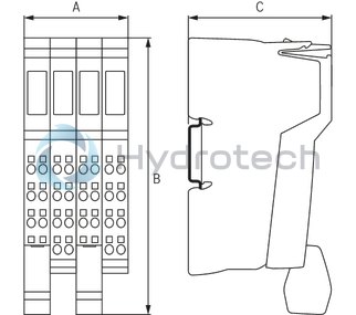
Dimensions
|
Type |
R-IB IL SGI 2/F-PAC | |
|
A |
mm |
48.8 |
|
B |
mm |
136.8 |
|
C |
mm |
72 |
|
Note on dimensions |
The depth applies when using a support rail TH 35-7.5 (acc. to EN 60715). | |