


BOSCH REXROTH
R901466598
$428.00 USD
- BOSCH REXROTH
- Material:R901466598
- Model:HM20-2X/400-H-K35-N
Quantity in stock: 0
The Bosch Rexroth HM 20-2X/400-H-K35-N (R901466598) is a high-performance pressure transducer designed for dynamic pressure control in hydraulic systems. This robust sensor is capable of measuring pressures up to 400 bar with a fast signal rise time of less than 2 ms, ensuring timely and accurate readings for real-time applications. The HM 20-2X/400-H-K35-N features a thin-film measuring cell and all media-contacting components are constructed from durable stainless steel, which provides a high degree of measurement accuracy of less than ±0.5% FS. The unit's excellent overload and bursting behavior make it suitable for demanding environments where operational safety is critical. It offers protection against reversed polarity, overvoltage, and short circuiting, which contributes to its reliability. The analog output of 0...10 V from the transducer allows for easy integration into existing control systems. With an operational temperature range from -40°C to +125°C, the HM 20-2X/400-H-K35-N is versatile enough to function effectively in varied climates and conditions. It comes with an M12x1 A-coded connector as per EN 175301-803 standards for the electrical connection and has no display component. The supply voltage required is 24 VDC, and the unit weighs approximately 0.4 kg. This sensor uses NBR seals and can handle hydraulic fluids such as HL, HLP, HFC, as well as nitrogen up to pressures of 400 bar. It meets several conformity standards including CE for electromagnetic compatibility, RoHS Directive EU for hazardous substances, UL recognition for safety standards in North America, and UKCA marking post-Brexit. Additionally, it has received marine approval from DNVGL when used with current output options, highlighting its suitability for maritime applications where reliable pressure measurement is essential.
Pressure transducer with analog output 0.1 … 10 V, pressure range 0 ... 400 bar, connector 4-pole M12x1 A-coded, throttle element
Short signal rise time
Unpacked Weight: 0.062 kg
Pressure transducers are used to monitor and control hydraulic pressures. They transform the measured pressure into a normalized, linear, electrical output signal.
| Thin film measuring cell |
| Hydraulic connection G1/4 |
| Throttle element in the pressure tube |
| Analog output 0.1 … 10 V |
| Throttle element in the pressure channel |
| Connector 4-pole, M12x1, A-coded |
| Component series 2X |
| Data Sheet | Download Data Sheet |
| 3D CAD | Download 3D CAD |
| 3D CAD | Download 3D CAD |
| Max. pressure | 400 |
| Electrical connection description | Connector, 4-pole, M12 x 1, coding A according to EN 61076-2-101 |
| Productgroup ID | 9,10,11,12,13,14 |
| Conformity description | CE – electromagnetic compatibility 2014/30/EU RoHS Directive 2011/65/EU |
| Display | no |
| Connection diagram | Male thread G1/4 |
| Supply voltage | 24 VDC |
| Weight | 0.062 |
| Seals | NBR |
| Output signal | 0.1 … 10 V |
| Hydraulic fluid | HL,HLP,HFC,Nitrogen (up to 300 bar) |
| Conformity | CE,UL,UKCA,RoHS |
|
01 |
02 |
03 |
04 |
05 |
06 |
||||
|
HM20 |
– |
2X |
/ |
– |
– |
K35 |
|
01 |
Pressure transducer |
HM20 |
|
02 |
Component series 20 ... 29 (20 ... 29: unchanged installation dimensions and pin assignments) |
2X |
|
03 |
10 bar |
10 |
|
50 bar |
50 |
|
|
100 bar |
100 |
|
|
160 bar |
160 |
|
|
250 bar |
250 |
|
|
315 bar |
315 |
|
|
400 bar |
400 |
|
|
630 bar1) |
630 |
|
|
04 |
Current output 4 to 20 mA 2) |
C |
|
Voltage output 0.1 to 10 V |
H |
|
|
05 |
Connector, 4-pole, M12x1 |
K35 |
|
06 |
Without throttle element |
ohne Bez. |
|
Throttle element (corresponds to 0.3 mm nozzle) 3), 4) |
N |
| 1) | Only available with throttle element |
| 2) | With marine approval DNV-GL |
| 3) | Only available for versions with 250, 315, 400 and 630 bar |
| 4) | Highly dynamic effects in like pressure peaks or cavitation in hydraulic systems may damage the measuring cell. For these applications, devices with integrated throttle element [version "-N"] in the process interface have to be used. |
|
Replacement seal ring |
|
|
Designation |
Material number |
|
Seal ring NBR |
R900012467 |
Cable sets or mating connectors are not included in the scope of delivery; please order separately.
General
|
Component series |
2X |
Eingangsgrößen
|
Operating voltage 1) |
US |
16 … 36 VDC | ||||||||||||||||||||||||||||||||||||||||||||||||||||||||||||||||
|
Residual ripple |
UPP |
2.5 V (40 to 400 Hz) | ||||||||||||||||||||||||||||||||||||||||||||||||||||||||||||||||
|
Maximum current consumption 2) |
Imax |
mA |
≤ 12 | |||||||||||||||||||||||||||||||||||||||||||||||||||||||||||||||
|
Isolation resistance |
R |
MΩ |
> 100 (500 VDC) | |||||||||||||||||||||||||||||||||||||||||||||||||||||||||||||||
|
Pressure measuring ranges |
pN |
bar |
10 | 50 | 100 | 160 | 250 | 315 | 400 | 630 | 10 | 50 | 100 | 160 | 250 | 315 | 400 | 630 | 10 | 50 | 100 | 160 | 250 | 315 | 400 | 630 | 10 | 50 | 100 | 160 | 250 | 315 | 400 | 630 | 10 | 50 | 100 | 160 | 250 | 315 | 400 | 630 | 10 | 50 | 100 | 160 | 250 | 315 | 400 | 630 | 10 | 50 | 100 | 160 | 250 | 315 | 400 | 630 | 10 | 50 | 100 | 160 | 250 | 315 | 400 | 630 |
| 1) | With cULus: max. of 30 VDC is admissible |
| 2) | With voltage output |
Output parameters
|
Output signal |
admissible load |
Current |
ISig |
4 … 20 mA, RA = (US - 8.5 V) / 0.0215 A with RA in Ω and US in V | |
|
Voltage |
USig |
0.1 … 10 V, RA > 2 kΩ | |||
|
Setting time (10 ... 90 %) |
t |
ms |
< 1 | ||
|
Accuracy class 1) |
% |
< 0.5 | |||
|
Temperature coefficient |
Zero point and range |
< 0.1 % / 10 K | |||
|
Hysteresis 2) |
% |
< 0.15 | |||
|
Long-term drift (1 year) under reference conditions |
% |
< 0.1 | |||
| 1) | Related to the complete measurement range, including non-linearity, hysteresis, zero point and end value deviation (corresponds to the measuring deviation according to IEC 61298-2) |
| 2) | Related to the temperature range -20 … 80 °C |
Ambient conditions
|
Ambient temperature range |
ϑ |
°C |
-40 … +85 |
|
Storage temperature range |
ϑ |
°C |
-40 … +100 |
|
Hydraulic fluid temperature range |
ϑ |
°C |
-40 … +90 |
Other characteristics
|
Pressure port 1) |
G1/4 according to DIN 3852 form E, seal ring according to DIN 3869-14 | |||
|
Material |
Throttle |
1.4305 | ||
|
Housing |
V4A (1.4404), PEI, HNB | |||
|
in contact with the medium |
1.4542, 1.4305, NBR | |||
|
Pressure media 2) |
HL, HLP, HFC, nitrogen, others upon request | |||
|
Tightening torque range |
Measurement ranges > 400 bar |
MA |
Nm |
20 … 25 |
|
Measurement ranges ≥ 400 bar |
MA |
Nm |
25 … 30 | |
|
Anschlussart |
4-pole M12 connector at the housing | |||
|
Type of protection according to EN 60529 |
IP65 / IP67 with mating connector correctly mounted and locked | |||
|
Weight |
m |
kg |
0.06 | |
|
Life cycle |
60 million load cycles or 60000 h | |||
|
Admissible shock and vibration loads according to DIN EN 60068-2-27 |
15 g / 11 ms / 3 axes | |||
|
Sine test according to DIN EN 60068-2-6:2008 |
10 ... 2000 Hz / maximum 10 g / 10 cycles / 3 axes | |||
|
Noise test according to DIN EN 60068-2-64 |
20 … 2000 Hz / 14 g RMS / 42 g peak / 24 h / 3 axes | |||
|
Electro-magnetic compatibility |
EMC EN 61000-4-2 ESD |
4 kV CD / 8 kV AD with BWK B | ||
|
EMC EN 61000-4-3 HF radiated |
10 V / m (80 ... 2700 MHz) with BWK A | |||
|
EMC EN 61000-4-4 Burst |
2 kV with BWK B | |||
|
EMC EN 61000-4-5 Surge |
1 kV / 42 Ω with BWK B | |||
|
EMC EN 61000-4-6 HF line-bound |
10 Veff (150 kHz ... 80 MHz) with BWK A | |||
|
EMC EN 61000-4-8 Magnetic field 50/60 Hz |
100 A/m with BWK A | |||
|
EMC EN 61000-4-9 Magnetic field pulsed |
1000 A/m with BWK A | |||
|
EMC EN 55016-2-1 Interference voltage |
0.15 ... 30 MHz, class A, EN 55022 | |||
|
EMC EN 55016-2-3 Radio interference field strength |
30 ... 1000 MHz, class B, EN 55022 | |||
|
Conformity |
CE according to the EMC directive | |||
|
Further tests |
cULus-listed | |||
| 1) | Thorough bleeding must be ensured |
| 2) | Maximum of 300 bar is admissible |
For applications outside these parameters, please consult us!
|
Voltage |
Current (two-wire system) |
Values for US, RA and USig, see Technical data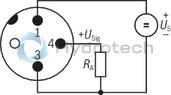
|
Values for US, RA and USig, see Technical data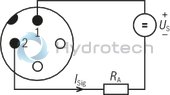
|
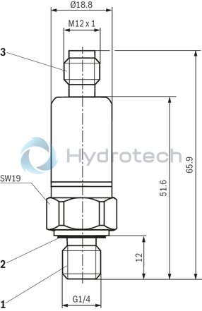
Dimensions in mm
|
1 |
Pressure port G1/4 male thread |
|
2 |
Seal ring |
|
3 |
4-pole M12 connector |
Mating connectors for sensors and valves with connector “K24”, “K35” and “K72”, M12 x 1, with assembled connection line, cable shielded
4P M12 +
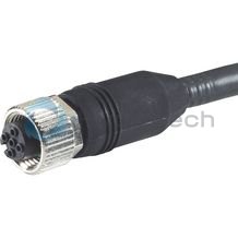
Mating connectors for sensors and valves with connector “K24”, “K35” and “K72”, M12 x 1, with assembled connection line, cable shielded
4P M12 +
For sensors and valves with connector “K24”, “K35” and “K72” Cable sets M12, 4-pole, line cross-section 0.34 mm2Data sheet
Spare parts & repair