


BOSCH REXROTH
R901454191
$276.19 USD
- BOSCH REXROTH
- Material:R901454191
- Model:S 25 A15-1X/420J3/12
Quantity in stock: 0
The Bosch Rexroth S25A15-1X/420J3/12 (R901454191) is a high-quality check valve designed for threaded connections, ensuring leak-free blocking in one direction. This precision-engineered valve is part of the Component series X and is characterized by its robustness and reliability in controlling fluid flow within hydraulic systems. The valve has been crafted to withstand a maximum operating pressure of up to 420 bar, which makes it suitable for use in demanding applications requiring high-pressure capabilities. The model boasts an impressive maximum flow rate, accommodating the efficient management of fluid dynamics within a system. Users have the flexibility to choose from various cracking pressures according to their specific requirements, thanks to the optional range provided by Bosch Rexroth. This feature allows for customization and optimization of system performance based on the operational needs. The S25A15-1X/420J3/12 check valve's functionality is essential in hydraulic circuits where it prevents reverse flow, thereby protecting sensitive components and maintaining the desired direction of fluid movement. Its precise construction ensures that it operates seamlessly within the system, contributing to the overall efficiency and safety of hydraulic operations. With its specialized design and robust construction, this Bosch Rexroth check valve is an indispensable component for professionals seeking reliable hydraulic control solutions.
|
01 |
02 |
03 |
04 |
05 |
06 |
07 |
08 |
09 |
||
|
S |
A |
- |
1X |
/ |
|
Type |
||
|
01 |
Isolator valve |
S |
|
Size |
||
|
02 |
Size 6 |
6 |
|
Size 8 |
8 |
|
|
Size 10 |
10 |
|
|
Size 15 |
15 |
|
|
Size 20 |
20 |
|
|
Size 25 |
25 |
|
|
Size 30 |
30 |
|
|
Connection |
||
|
03 |
Threaded connection |
A |
|
Cracking pressure (see characteristic curves) |
||
|
04 |
0 bar (without spring) |
00 |
|
0,2 bar |
02 |
|
|
0.5 bar (standard) |
05 |
|
|
1,5 bar |
15 |
|
|
3,0 bar |
30 |
|
|
5 bar |
50 |
|
|
8 bar (only NG25 and 30) |
80 |
|
|
Component series |
||
|
05 |
Component series 10 ... 19 (10 ... 19: unchanged installation and connection dimensions) |
1X |
|
Maximum operating pressure |
||
|
06 |
Maximum operating pressure 420 bar (Nominal size 25 and 30) |
420 |
|
Maximum operating pressure 450 bar (Nominal size 6 ... 20) |
450 |
|
|
Corrosion resistance |
||
|
07 |
Improved corrosion protection (240 h salt spray test according to EN ISO 9227) |
J3 |
|
High corrosion protection (720 h salt spray test according to EN ISO 9227) |
J5 |
|
|
Piston bore (orifice in channel B) |
||
|
08 |
Without piston bore |
no code |
|
Thread M4; not fitted |
B00 |
|
|
Orifice Ø1.0 mm |
B10 |
|
|
Orifice Ø1.2 mm |
B12 |
|
|
Orifice Ø1.5 mm |
B15 |
|
|
Connection thread 1) |
||
|
09 |
Pipe thread "G" according to ISO 228-1 |
no code |
|
Pipe thread "M" according to ISO 261 |
/2 |
|
|
Pipe thread “UNF/UN” according to ANSI/ASME B 1.1 |
/12 |
|
| 1) | Other versions available on request |
general
|
Size |
6 | 8 | 10 | 15 | 20 | 25 | 30 | |
|
Weight |
kg |
0.1 | 0.2 | 0.3 | 0.5 | 1 | 2 | 2.5 |
|
MTTFD values according to EN ISO 13849 |
Years |
150 1) | ||||||
| 1) | Not for version "00"; Certificate "Assumed exclusion of faults according to EN ISO 13849-2:2012-10 tab. C4" available upon request. For further details, see data sheet 08012 |
hydraulic
|
Size |
6 | 8 | 10 | 15 | 20 | 25 | 30 | |
|
Maximum operating pressure 1) |
bar |
450 | 420 | |||||
|
Cracking pressure |
See characteristic curves | |||||||
|
Maximum flow |
See characteristic curves | |||||||
|
Hydraulic fluid |
see table | |||||||
|
Hydraulic fluid temperature range |
°C |
-30 … +80 | ||||||
|
Viscosity range |
mm²/s |
2.8 … 500 | ||||||
|
Maximum admissible degree of contamination of the hydraulic fluid 2) |
Class 20/18/15 according to ISO 4406 (c) | |||||||
| 1) | Maximum operating pressures up to 1000 bar upon request. |
| 2) | The cleanliness classes specified for the components must be adhered to in hydraulic systems. Effective filtration prevents faults and simultaneously increases the life cycle of the components. For the selection of the filters, see www.boschrexroth.com/filter. |
|
Hydraulic fluid |
Classification |
Standards |
Data sheet |
|
|
Mineral oils |
HL,HLP, HLPD, HVLP, HVLPD |
DIN 51524 |
90220 |
|
|
Bio-degradable 1) |
Insoluble in water |
HETG |
ISO 15380 |
90221 |
|
HEES |
||||
|
Soluble in water |
HEPG |
ISO 15380 |
||
|
Flame-resistant |
Water-free |
HFDU (glycol base) |
||
|
HFDU (ester base) 1) |
ISO 12922 |
90222 |
||
|
Containing water 1) |
HFC (Fuchs Hydrotherm 46M, Petrofer Ultra Safe 620) |
ISO 12922 |
90223 |
|
|
Important information on hydraulic fluids: For further information and data on the use of other hydraulic fluids, please refer to the data sheets above or contact us. There may be limitations regarding the technical valve data (temperature, pressure range, life cycle, maintenance intervals, etc.). The ignition temperature of the hydraulic fluid used must be 50 K higher than the maximum surface temperature. Flame-resistant – containing water: Life cycle as compared to operation with mineral oil HL, HLP 30 … 100% Maximum hydraulic fluid temperature 60 °C |
||||
| 1) | Small amounts of dissolved zinc may get into the hydraulic system during use. |
For applications outside these parameters, please consult us!
(measured with HLP46, ϑOil = 40 ±5 °C)
∆p-qV characteristic curves with cracking pressure
Size 6
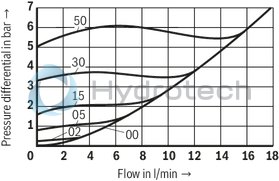
Size 8
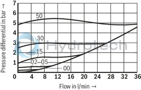
Size 10
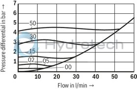
Size 15
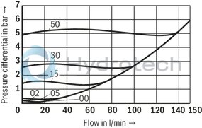
Size 20
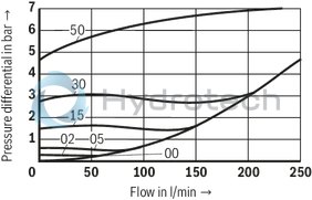
Size 25
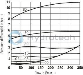
Size 30
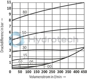
Without spring

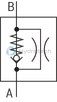
With spring

With piston bore/orifice
Dimensions in mm
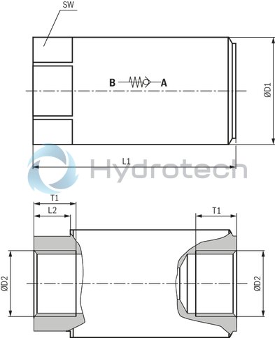
|
NG |
6 | 8 | 10 | 15 | 20 | 25 | 30 | |||
|
ØD1 |
mm |
22.5 | 28 | 34 | 34 | 42 | 52 | 68 | 74.5 | |
|
D2 |
G |
G1/4 | G3/8 | - | G1/2 | G3/4 | G1 | G1 1/4 | G1 1/2 | |
|
M |
M14 x 1,5 | M18 x 1,5 | - | M22 x 1.5 | M27 x 2 | M33 x 2 | M42 x 2 | M48 x 2 | ||
|
UNF/UN |
- | - | 3/4-16 UNF | 3/4-16 UNF | 1 1/6-12 UN | 1 5/16-12 UN | 1 5/8-12 UN | 1 7/8-12 UN | ||
|
L1 |
G |
mm |
58 | 58 | - | 72 | 88 | 98 | 120 | 132 |
|
M |
mm |
58 | 58 | - | 72 | 88 | 98 | 120 | 132 | |
|
UNF/UN |
mm |
- | - | 66 | 72 | 92 | 105 | 120 | 132 | |
|
L1 |
mm |
- | 160 1) | 168 1) | ||||||
|
L2 |
mm |
10.5 | 11.5 | 13 | 13 | 15.5 | 19 | 25 | 28 | |
|
T1 |
G |
mm |
13 | 13 | - | 15 | 18 | 19 | 22 | 22.5 |
|
M |
mm |
12 | 12 | - | 14 | 16 | 18 | 20 | 22 | |
|
UNF/UN |
mm |
- | - | 15 | 15 | 20 | 20 | 20 | 20 | |
|
SW |
G |
mm |
19 | 24 | 30 | 30 | 36 | 46 | 60 | 65 |
| 1) | Version "...A80..." |