

BOSCH REXROTH
R901411436
$1,608.77 USD
- BOSCH REXROTH
- Material:R901411436
- Model:3DREP6A-2X/16EG24K4/M-674
Quantity in stock: 0
The Bosch Rexroth 3DREP6A-2X/16EG24K4/M-674 (R901411436) is a state-of-the-art direct operated proportional pressure reducing valve designed to convert electric input signals into proportional pressure output signals. This valve is engineered for precision in controlling the pressure and direction of fluid flow within hydraulic systems. It features wet-pin DC solenoids that can be controlled either by an external control electronics type DREP or by integrated control electronics type DREPE. The valve consists of a housing with a connection surface, a control spool with a pressure measuring spool, and solenoids with central threads that can be optionally accompanied by integrated control electronics. The functionality of the 3DREP6A-2X/16EG24K4/M-674 allows for the setting of pressure in ports A or B through the proportional solenoids, with the actual pressure dependent on the current supplied to the solenoids. With no current, the compression springs hold the control spool in a central position, allowing hydraulic fluid to return to the tank unimpeded. When energized, one of the solenoids moves the control spool, thereby adjusting the connection from P to B and A to T through progressive flow characteristics. The pressure is balanced against solenoid force and measured by the pressure measuring spool. An optional hand override feature allows manual adjustment without energizing solenoids; however, caution must be exercised as accidental activation can lead to unintended machine movements. This valve supports two spool positions (type DREP..A.. or DREP..B..) and may come with one active solenoid while using a plug screw in place of a second proportional solenoid. It is crucial that tank lines are not allowed to run empty; installation conditions might require a preload valve with approximately 5 bar preload pressure. The Bosch Rexroth 3DREP6A-2X/16EG24K4/M-674 offers robust performance specifications such as compatibility for subplate mounting following ISO standards, an optional manual override for increased control flexibility, spring-centered control spools for stability, and integrated or external electronic options for diverse application needs. It's suitable for high-pressure applications up to 315 bar with maximum flow rates up to 16 liters per minute.
The 3-way pressure reducing valve type 3 DREP 6.. is direct operated by proportional solenoids. It is intended for the conversion of an electric input signal into a proportional pressure output signal. The proportional solenoids are controllable, wet-pin DC solenoids with a central thread and a detachable coil. The solenoids are controlled optionally either by external control electronics (type 3DREP) or by the integrated control electronics (type 3DREPE).
Set-up:
The valve basically consists of:
Housing (1) with connection surface Control spool (2) with pressure measuring spool (3, 4) Solenoids (5, 6) with central thread optional integrated control electronics (7)Function:
The pressure in A or B is set by means of the proportional solenoids. The amount of the pressure depends on the current. With de-energized solenoids (5, 6), the control spool (2) is held in the central position by means of the compression springs (8). Ports A and B are connected with T so that the hydraulic fluid can flow to the tank without obstructions. By energizing a proportional solenoid, e.g. solenoid "a" (5), the pressure measuring spool (3) and with it the control spool (2) are moved to the right. This opens the connection from P to B and A to T via orifice-type cross-sections with progressive flow characteristics. With the surface of the pressure measuring spool (4) the pressure that builds up in channel B acts on the control spool and against the solenoid force. The pressure measuring spool (4) is supported by solenoid "b". If the pressure exceeds the value set at solenoid "a", the control spool (2) is pushed back against the solenoid force and connects B with T until the set pressure is reached again. The
pressure is proportional to the solenoid current. When the solenoid is switched off, the control spool (2) is returned into the central position by the compression springs (8). An optional hand override (9, 10) allows control spool (2) to be moved without solenoid energization.
Notice:
Accidental activation of the hand override may lead to uncontrolled machine movements!
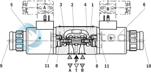

Valve with two spool positions (type 3DREP..A.. or 3DREP..B..):
The function of this valve version basically corresponds to the valve with three spool positions. The 2 spool position valve is, however, only equipped with solenoid “a” (5) or solenoid “b” (6). Instead of the 2nd proportional solenoid, a plug screw (11) is installed.
Notice:
The tank line must not be allowed to run empty. With corresponding installation conditions, a preload valve (preload pressure approx. 2 bar) must be installed.
|
01 |
02 |
03 |
04 |
05 |
06 |
07 |
08 |
09 |
10 |
11 |
12 |
13 |
14 |
|||
|
3DREP |
6 |
‒ |
2X |
/ |
E |
G24 |
/ |
* |
|
01 |
Proportional pressure relief valve in 3-way version |
3DREP |
|
|
02 |
For external analog electronics |
no code |
|
|
With integrated control electronics |
E |
||
|
03 |
Size 6 |
6 |
|
|
Version |
|||
|
04 |
Type 3DREP6 A 2X/..
|
A |
|
Type 3DREP6 B 2X/..
|
B |
||
Type 3DREP6 C 2X/..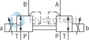
|
C |
||
|
05 |
Component series 20 ... 29 (20 ... 29: unchanged installation and connection dimensions) - Size 6 |
2X |
|
|
Pressure rating |
|||
|
06 |
16 bar |
16 |
|
|
25 bar |
25 |
||
|
45 bar |
45 |
||
|
07 |
Proportional solenoid with detachable coil |
E |
|
|
Power supply |
|||
|
08 |
Direct voltage 24 V |
G24 |
|
|
09 |
Without manual override |
no code |
|
|
With concealed manual override |
N9 3) |
||
|
10 |
Without special type of protection |
no code |
|
|
Sea water-resistant |
J 2) |
||
|
Electrical connection |
|||
|
11 |
For type DREP: |
Without mating connector; connector DIN EN 175301-803 |
K4 1) |
|
For type DREPE: |
Without mating connector; connector DIN EN 175201-804 |
K311) |
|
|
Electrical interface |
|||
|
12 |
For type DREP: |
no code |
|
|
For type DREPE: |
Command value/actual value ±10 V |
A1 |
|
|
Command value/actual value 4 … 20 mA |
F1 |
||
|
Seal material |
|||
|
13 |
NBR seals |
M |
|
|
FKM seals |
V |
||
|
14 |
Further details in the plain text |
* |
|
|
1) |
For version "J" = seawater-resistant only indicate "K31" |
||
|
2) |
Only for version 3DREP6 |
||
|
3) |
With version “J”, indicate “N” only instead of “N9” |
||
|
Special electrical types of protection upon request |
|||
For applications outside these parameters, please consult us!
general
|
Type |
3DREP | 3DREPE | |
|
Size |
6 | ||
|
Component series |
2X | ||
|
Installation position |
any, preferably horizontal | ||
|
Earth |
kg |
2 | 2.2 |
|
Storage temperature range |
°C |
-20 … +80 | |
|
Ambient temperature range |
°C |
-20 … +70 | -20 … +50 |
hydraulic
|
Type |
3DREP | 3DREPE | |||
|
Maximum operating pressure |
bar |
100 | |||
|
Operating pressure range |
Port P |
Pressure rating 16 bar |
bar |
20 … 100 | |
|
Pressure rating 25 bar |
bar |
30 … 100 | |||
|
Pressure rating 45 bar |
bar |
50 … 100 | |||
|
Port T |
bar |
0 ... 30 | |||
|
Maximum flow 1) |
l/min |
15 | 15 | ||
|
Hydraulic fluid |
see table | see table | |||
|
Hydraulic fluid temperature range |
°C |
-20 … +80 | -20 … +80 | ||
|
Viscosity range |
mm²/s |
20 … 380 | 20 … 380 | ||
|
preferably |
mm²/s |
30 … 46 | 30 … 46 | ||
|
Maximum admissible degree of contamination of the hydraulic fluid, cleanliness class according to ISO 4406 (c) 2) |
Class 17/15/12 according to ISO 4406 (c) | Class 17/15/12 according to ISO 4406 (c) | |||
|
Hysteresis |
% |
≤ 5 | ≤ 5 | ||
|
Repetition accuracy |
% |
≤ 1 | ≤ 1 | ||
|
Response sensitivity |
% |
≤ 0.5 | ≤ 0.5 | ||
|
Range of inversion |
% |
≤ 1 | ≤ 1 | ||
| 1) | Δp = 50 bar |
| 2) | The cleanliness classes specified for the components must be adhered to in hydraulic systems. Effective filtration prevents faults and simultaneously increases the life cycle of the components. For the selection of the filters, see www.boschrexroth.com/filter. |
|
Hydraulic fluid |
Classification |
Suitable sealing materials |
Standards |
|
Mineral oils and related hydrocarbons |
HL, HLP |
NBR / FKM |
DIN 51524 |
|
Flame-resistant - containing water |
HFC
|
NBR |
ISO 12922 |
|
Important information on hydraulic fluids: For more information and data on the use of other hydraulic fluids please contact us. There may be limitations regarding the technical valve data (temperature, pressure range, life cycle, maintenance intervals, etc.). The flash point of the process and operating medium used must be 40 K over the maximum solenoid surface temperature.
Flame-resistant - containing water: |
|||
electrical
|
Type |
3DREP | 3DREPE | ||
|
Voltage type |
Direct voltage | |||
|
Type of signal |
analog | |||
|
Maximum solenoid current |
A |
1.5 | 2.5 | |
|
Solenoid coil resistance |
Cold value at 20 °C |
Ω |
5.2 | 2.15 |
|
Maximum hot value |
Ω |
7.6 | 3.3 | |
|
Duty cycle |
% |
100 | ||
|
Coil temperature 1) |
°C |
150 | ||
|
Protection class according to DIN EN 60529 |
IP65 (with mating connector mounted and locked) | |||
| 1) | Due to the surface temperatures of the solenoid coils, the standards ISO 13732-1 and EN 982 need to be adhered to! |
(measured with HLP46, ϑOil = 40 ±5 °C)
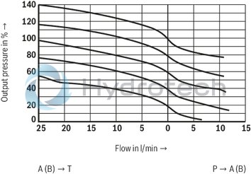
Pressure rating 16, 25, and 45 bar
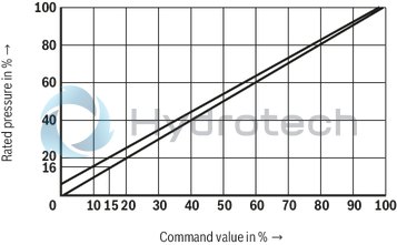
Pressure rating 16, 25, and 45 bar
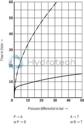
Flow-dependent pressure
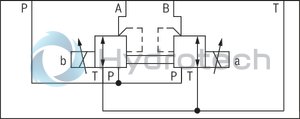
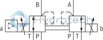
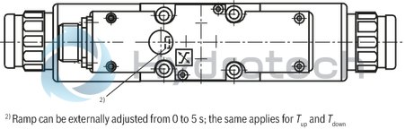
Type 3DREP..6 A 2X/..E (detailed)

Type 3DREP..6 B 2X/..E (detailed)

Type 3DREP..6 C 2X/..E (detailed)
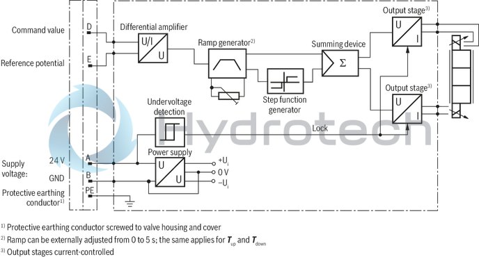
Example of valve with integrated control electronics; type 3DREPE..6 C 2X/..E (simplified)
|
Pin assignment |
Contact |
Assignment interface "A1" |
Assignment interface "F1" |
|
Power supply |
A |
24 VDC (u(t) = 19,4 ... 35 V); Imax = 2 A |
|
|
B |
0 V |
||
|
Reference potential actual value |
C |
cannot be used 1) |
|
|
Differential amplifier input (command value) |
D |
±10 V command value; Re > 50 kΩ |
4 ...20 mA command value; Re > 100 Ω |
|
E |
Reference potential command value |
||
|
Measuring output (actual value) |
F |
cannot be used 1) |
|
|
PE |
connected to cooling element and valve housing |
||
|
1) |
Contacts C and F must not be connected! |
||
Command value:
Reference potential at E and positive command value (or 12...20 mA) at D result in pressure in A.
Reference potential at E and negative command value (or 12...4 mA) at D result in pressure in B.
With valves with solenoid on side “b” (version A), reference potential at E and a positive command value at D (4...20 mA) result in pressure in A.
With valves with solenoid on side “a” (version B), reference potential at E and a positive command value at D (4...20 mA) result in pressure in B.
Connection cable:
Recommendation:
up to 25 m line length: Type LiYCY 5 x 0.75 mm2 up to 50 m line length: Type LiYCY 5 x 1.0 mm2 External diameter 6.5 to 11 mm Connect shield to PE on the supply side.Block diagram / pin assignment
|
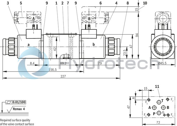
1 |
Valve housing |
|
2 |
Name plate |
|
3 |
Proportional solenoid "a" |
|
4 |
Proportional solenoid "b" |
|
5 |
Mating connector "A", color gray, separate order |
|
6 |
Mating connector "B", color black, separate order |
|
7 |
Identical seal rings for ports A, B, P, and T |
|
8 |
Concealed manual override “N9” |
|
9 |
Plug screw for valve with one solenoid |
|
10 |
Space required to remove the mating connector |
|
11 |
Machined valve contact surface; Porting pattern according to ISO 4401-03-02-0-05 |
|
1 |
Valve housing |
|
2 |
Name plate |
|
3 |
Proportional solenoid "a" |
|
4 |
Proportional solenoid "b" |
|
5 |
Mating connector according to DIN EN 175201-804, separate order |
|
7 |
Identical seal rings for ports A, B, P, and T |
|
8 |
Concealed manual override “N” |
|
9 |
Plug screw for valve with one solenoid |
|
10 |
Space required to remove the mating connector |
|
11 |
Machined valve contact surface; Porting pattern according to ISO 4401-03-02-0-05 |
|
12 |
Dimension for version "N" |

|
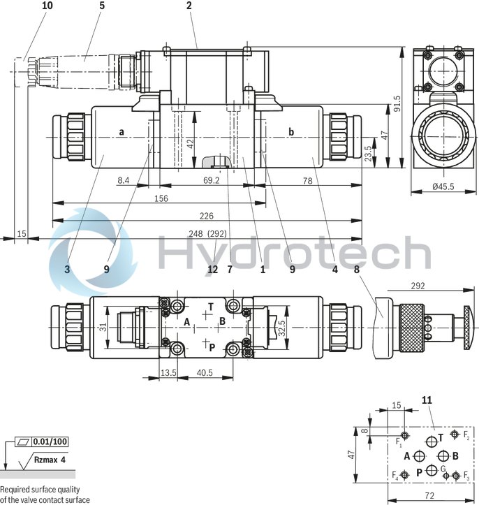
1 |
Valve housing |
|
2 |
Name plate |
|
3 |
Proportional solenoid "a" |
|
4 |
Proportional solenoid "b" |
|
5 |
Mating connector according to DIN EN 175201-804, separate order |
|
7 |
Identical seal rings for ports A, B, P, and T |
|
8.1 |
Concealed manual override “N9” |
|
8.2 |
Manual override “N“ for seawater-resistant version "J" |
|
9 |
Plug screw for valve with one solenoid |
|
10 |
Space required to remove the mating connector |
|
11 |
Machined valve contact surface; Porting pattern according to ISO 4401-03-02-0-05 |
|
12 |
Integrated electronics (OBE) |
|
13 |
Dimension for seawater-resistant version "J" |
Recommended valve mounting screws (separate order):
4 hexagon socket head cap screws ISO 4762 - M5 x 50 - 10.9Tightening torque MA = 8.9 Nm ± 10%
Mating connectors for valves with connector “K4”, without circuitry, standard
3P Z4
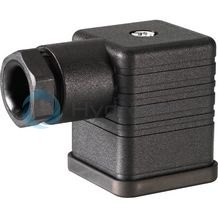
Mating connectors for valves with connector “K4”, without circuitry, standard
3P Z4
For valves with connector “K4” according to EN 175301-803 and ISO 4400, 2-pole + PE, “large cubic connector” Mating connectors for valves with one or two solenoids (individual connection)Data sheet
Spare parts & repair
Mating connectors for valves with round connector, 6-pole + PE
7P Z31
Mating connectors for valves with round connector, 6-pole + PE
7P Z31
For valves with round connector according to EN 175201-804, 6-pole + PE as well as 6-pole, compatible with VG 95328Data sheet
Spare parts & repair