

BOSCH REXROTH
R901364152
$3,151.01 USD
- BOSCH REXROTH
- Material:R901364152
- Model:M-3SMR6C3X/420/B12V
Quantity in stock: 0
The Bosch Rexroth M-3SMR6C3X/420/B12V (R901364152) is a direct operated directional seat valve known for its robust performance and reliability in controlling the start, stop, and direction of fluid flow within hydraulic systems. This model features mechanical actuation through a roller plunger, offering precise operation and ensuring safe switching even after prolonged periods under pressure. Equipped with a porting pattern that adheres to DIN standards (form A without locating hole), the valve is designed to integrate seamlessly into various hydraulic circuits. The M-3SMR6C3X/420/B12V has a size of 6, belonging to component series X, which signifies its design iteration and compatibility. It can withstand a maximum operating pressure of up to 420 bar and is capable of handling a maximum flow rate as specified by the manufacturer. This valve's construction includes a hardened valve system with a ball or spool as the closing element, which is pressed onto the seat by springs in its initial position. The actuating force acts via this ball on an actuating plunger that is sealed on both sides. The chamber between the two sealing elements is connected to port P, making the valve system pressure compensated relative to the actuating forces or return spring. An optional feature for this model includes an inductive position switch that allows for contactless detection of the valve's position, enhancing operational safety and providing feedback for automated systems. It should be noted that this type of directional seat valve has negative spool overlap; thus, port T must always be connected. During switching processes from one seat opening to another’s closure, ports P-A-T may briefly interconnect—though this happens so swiftly it's generally inconsequential for most applications. For specific applications requiring controlled flow rates or leak-free closure from A to P, throttle inserts or check valve inserts can be employed respectively. These inserts are placed into port P of either the seat valve or an additional Plus plate depending on configuration needs. The Bosch Rexroth M-3SMR6C3X/420/B12V directional seat valve stands out for its durability and adaptability in various hydraulic control tasks with its advanced features and optional enhancements offering flexibility for tailored hydraulic solutions.
2/2 and 3/2 directional seat valve
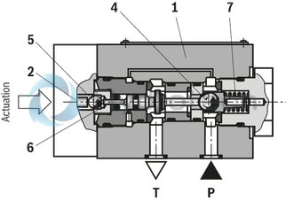
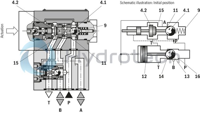
The directional valve of the M-.SMR type is a directional seat valve with manual, mechanical actuation. It controls start, stop and direction of flow and basically comprises of the housing (1), type of actuation (2), the hardened valve system (3) as well as the ball/the spool (4) as closing element.
Basic principle
In the initial position, the ball/the spool (4) is pressed onto the seat by the spring (7), and by the relevant type of actuation (2) in the switching position. The actuation force acts via the ball (5) on the actuating plunger (6) that is sealed on two sides. The chamber between the two sealing elements is connected to port P. Therefore, the valve system (3) is pressure-compensated in relation to the actuating forces (actuation or return spring). Therefore, the valves can be used up to 630 bar.
Notice!
3/2-directional seat valves feature "negative spool overlap". Therefore, port T must always be connected. That means that during the switching process – from the start of the opening of one valve seat to the closure of the other valve seat – ports P–A–T are connected with each other. However, this process takes place within such a short time that it is irrelevant in nearly all cases of use.
Attention!
It is to be ensured that the maximum flow indicated is not exceeded! If applicable, a throttle insert for flow limitation is to be inserted (see functional description).
The seat arrangement offers the following options:
|
2/2 directional seat valve |
|
|
Symbol “P” |
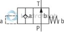
|
|
Initial position |
P and T connected |
|
Spool position |
P blocked |
|
Symbol “N” |
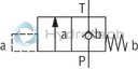
|
|
Initial position |
P blocked |
|
Spool position |
P and T connected |
|
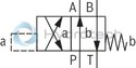
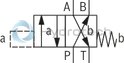
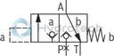
3/2 directional seat valve |
|
|
Symbol “U” |
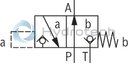
|
|
Initial position |
P and A connected, T blocked |
|
Spool position |
P blocked, A and T connected |
|
Symbol “C” |
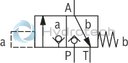
|
|
Initial position |
P blocked, A and T connected |
|
Spool position |
P and A connected, T blocked |
Type M-2S.. 6 N…
Type M-3S.. 6 U…
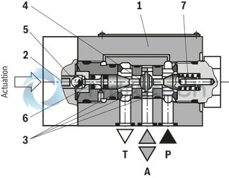
4/2 directional seat valve
With a sandwich plate, the Plus-1 plate, under the 3/2 directional seat valve, the function of a 4/2 directional seat valve is achieved.
Function of the Plus-1 plate:
Initial position
The main valve is not operated. The spring (9) holds the ball (4.1) on the seat (11). Port P is blocked and A is connected to T. Apart from that, one control line is connected from A to the large area of the control spool (12), which is thus unloaded to the tank. The pressure applied via P now pushes the ball (13) onto the seat (14). Now, P is connected to B, and A to T.
Transition position
When the main valve is actuated, the spool (4.2) is shifted against the spring (9) and pressed onto the seat (15). During this, port T is blocked, while P, A, and B are briefly connected to each other.
Spool position:
P is connected to A. As the pump pressure acts via A on the large area of the control spool (12), the ball (13) is pressed onto the seat (16). Thus, B is connected to T, and P to A. The ball (13) in the Plus-1 plate has a “positive spool overlap”.
In order to avoid pressure intensification when using differential cylinders, the annulus area of the cylinder must be connected at A.
The use of the Plus-1 plate and the seat arrangement offer the following options:
|
Symbol “D” |
|
|
Symbol “Y” |
|
Type M-4S.. 6 Y…
Throttle insert
The use of a throttle insert is required if, due to prevailing operating conditions, flows which exceed the performance limit of the valve can occur during the switching processes.
Examples:
Accumulator operation, use as pilot control valve with internal pilot fluid tapping.2/2 and 3/2 directional seat valve (see functional description)
The throttle insert is inserted into port P of the seat valve.
4/2 directional seat valve (see functional description)
The throttle insert is inserted into port P of the Plus-1 plate.
Check valve insert
The check valve insert allows a free flow from P to A and closes A to P in a leak-free form.
2/2- and 3/2 directional seat valve (see functional description)
The check valve insert is inserted into port P of the seat valve.
4/2 directional seat valve (see functional description)
The check valve insert is inserted into port P of the Plus-1 plate.
|
01 |
02 |
03 |
04 |
05 |
06 |
07 |
08 |
09 |
10 |
11 |
12 |
||
|
M |
– |
SMR |
3X |
/ |
* |
|
01 |
Mineral oil |
M |
||||
|
02 |
2 main ports (NG6 only) |
2 |
||||
|
3 main ports |
3 |
|||||
|
4 main ports |
4 |
|||||
|
03 |
Seat valve, direct operated |
SMR |
||||

|
Mechanically actuated (roller plunger) |
|||||
|
04 |
Size 6 |
6 |
||||
|
Size 10 |
10 |
|||||
|
05 |
Main ports |
2 1) |
3 |
4 |
||
|
Symbols |
|
● |
– |
– |
P |
|
|
|
● |
– |
– |
N |
||
|
|
– |
● |
– |
U |
||
|
|
– |
● |
– |
C |
||
|
|
– |
– |
● |
D |
||
|
|
● |
Y |
||||
|
● = available |
||||||
|
06 |
Component series 30 ... 39 (30 ... 39: unchanged installation and connection dimensions) |
3X |
||||
|
07 |
Without detent |
no code |
||||
|
08 |
Operating pressure 420 bar |
420 bar |
||||
|
Operating pressure 630 bar |
630 bar |
|||||
|
Additional equipment Inductive position switch |
||||||
|
09 |
Without position switch |
no code |
||||
|
Monitored spool position "a" |
QMAG24 |
|||||
|
Monitored spool position "b" |
QMBG24 |
|||||
|
10 |
Without check valve insert, without throttle insert |
no code |
||||
|
With check valve insert |
P |
|||||
|
Throttle Ø 1.2 mm |
B12 |
|||||
|
Throttle Ø 1.5 mm |
B15 |
|||||
|
Throttle Ø 1.8 mm |
B18 |
|||||
|
Throttle Ø 2.0 mm |
B20 |
|||||
|
Throttle Ø 2.2 mm |
B22 |
|||||
|
Other orifices on request |
||||||
|
Seal material |
||||||
|
11 |
NBR seals |
no code |
||||
|
FKM seals (other seals upon request) |
V |
|||||
|
Observe compatibility of seals with hydraulic fluid used. |
||||||
|
12 |
Further details in the plain text |
* |
||||
For applications outside these parameters, please consult us!
general
|
Size |
6 | 10 | ||
|
Weight |
2/2 directional seat valve |
kg |
1.5 | - |
|
3/2 directional seat valve |
kg |
1.5 | 2.45 | |
|
4/2 directional seat valve |
kg |
2.2 | 3.3 | |
|
Installation position |
any | |||
|
Ambient temperature range |
NBR seals |
°C |
-30 … +50 | |
|
FKM seals |
°C |
-20 … +50 | ||
|
Operating force |
Maximum |
N |
250 | |
hydraulic
|
Size |
6 | 10 | ||
|
Maximum operating pressure |
Port P |
bar |
420 630 |
|
|
Port A |
bar |
420 630 |
||
|
Port B |
bar |
420 630 |
||
|
Maximum flow |
l/min |
25 | 40 | |
|
Hydraulic fluid |
see table | |||
|
Hydraulic fluid temperature range |
NBR seals |
°C |
-30 … +80 | |
|
FKM seals |
°C |
-20 … +80 | ||
|
Viscosity range |
mm²/s |
2.8 … 500 | ||
|
Maximum admissible degree of contamination of the hydraulic fluid, cleanliness class according to ISO 4406 (c) 1) |
Class 20/18/15 according to ISO 4406 (c) | |||
| 1) | The cleanliness classes specified for the components must be adhered to in hydraulic systems. Effective filtration prevents faults and simultaneously increases the life cycle of the components. For the selection of the filters, see www.boschrexroth.com/filter. |
|
Hydraulic fluid |
Classification |
Suitable sealing materials |
Standards |
|
|
Mineral oil |
HL, HLP |
FKM, NBR |
DIN 51524 1) |
|
|
Bio-degradable |
Insoluble in water |
HEES (synthetic esters) 2) |
FKM |
VDMA 24568 |
|
HETG (rape seed oil) 1) |
FKM, NBR |
|||
|
Soluble in water |
HEPG (polyglycols) 2) |
FKM |
VDMA 24568 |
|
|
Other hydraulic fluids on request |
||||
| 1) Suitable for NBR and FKM seals | |
| 2) Suitable for FKM seals only |
Inductive position switch type QM: electrical connection
The electric connection is realized via a 4-pole mating connector (separate order) with connection thread M12 x 1.
electrical
|
Connection voltage (DC voltage) |
V |
24 | ||
|
Voltage tolerance (connection voltage) |
+30 %/-15 % | |||
|
Admissible residual ripple |
% |
≤ 10 | ||
|
Max. load capacity |
mA |
400 | ||
|
Switching outputs 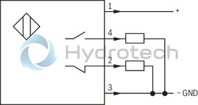
|
PNP transistor outputs, load between switching outputs and GND | |||
|
Pinout 
|
1 |
V |
24 | |
|
2, 4 |
Switching output |
mA |
400 | |
|
3 |
Earthing (GND) |
V |
0 | |
(measured with HLP46, ϑoil = 40 ± 5 °C)
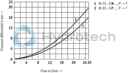
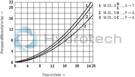
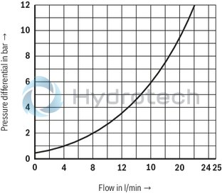
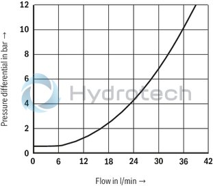
Δp-qV characteristic curve 2/2 directional seat valve (NG6)
3/2 directional seat valve (NG6)
4/2 directional seat valve (NG6)

Check valve insert (NG6)
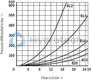
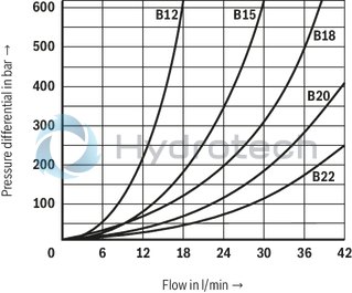
Throttle insert (NG6)
(measured with HLP46, ϑoil = 40 ± 5 °C)
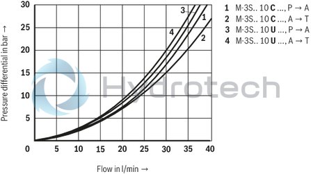
Δp-qV characteristic curve 3/2 directional seat valve (NG10)
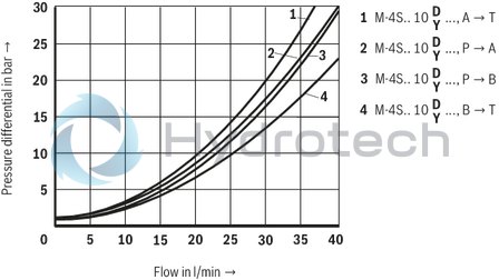
4/2 directional seat valve (NG10)
Check valve insert (NG10)
Throttle insert (NG10)
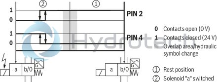
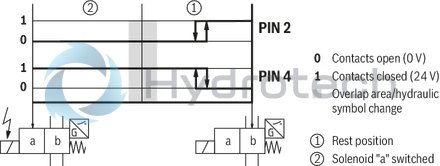
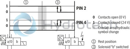
Inductive position switch type QM Switching logics
Version QMA
(Position switch on side B, monitored spool position "a")
Version QMA
(Position switch on side A, monitored spool position "a")
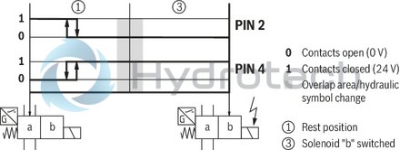
Version QMB
(Position switch on side B, monitored spool position "b")
Version QMB
(Position switch on side A, monitored spool position "b")
Performance limit (measured with HLP46, ϑoil = 40 ± 5 °C)
|
Symbol |
Comment |
||
|
2/2-way circuit (2/2 directional seat valve) |
P |
|
pP ≥ pT |
|
N |
|
||
|
2/2-way circuit (3/2 directional seat valve) as unloading function only |
U |

|
Before switching from the initial position to the switching position, pressure must be applied to port A. pA ≥ pT |
|
C |
|
pA ≥ pT |
|
|
3-way circuit |
U |
|
pP ≥ pA ≥ pT |
|
C |
|
||
|
4-way circuit (flow only possible in the direction of arrow) |
D |
|
3/2 directional valve (symbol “U”) in connection with Plus-1 plate: pP > pA ≥ pB > pT |
|
Y |
|
3/2 directional valve (symbol “C”) in connection with Plus-1 plate: pP > pA ≥ pB > pT |
|
Attention!
Please observe the “General notices”!
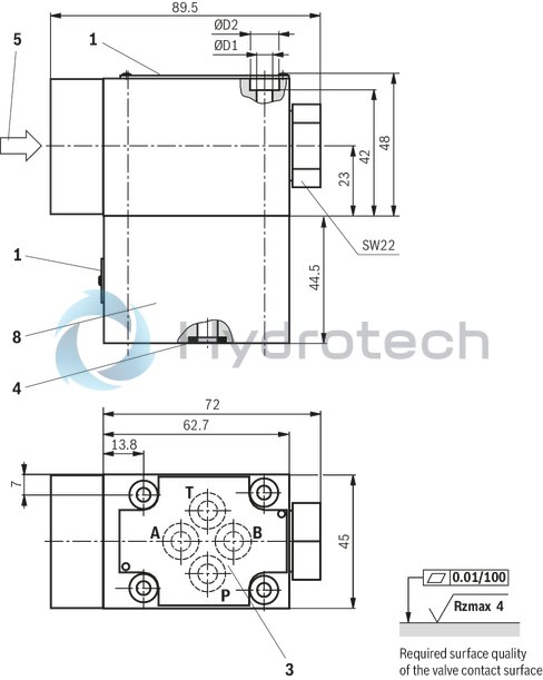
2/2, 3/2 directional seat valve – NG6
Dimensions in mm
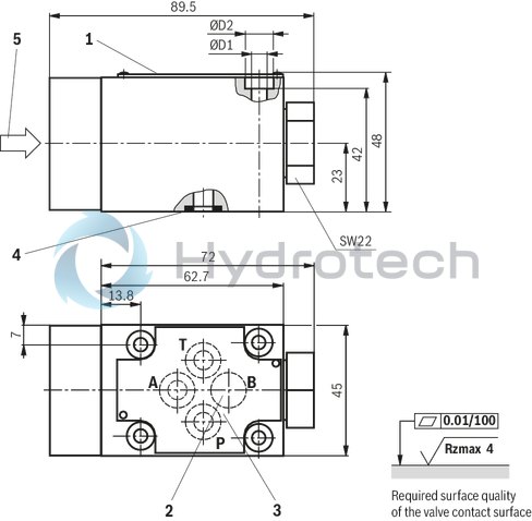
|
Operating pressure |
ØD1 |
ØD2 |
|
mm |
mm |
|
| 420 bar | 5.3 | 10 |
| 630 bar | 6.5 | 11 |
|
1 |
Name plate |
|
2 |
Attention!With 3/2 and 4/2 directional seat valves, port B is not available in 420 bar version as blind counterbore, in 630 bar version. |
|
3 |
Porting pattern according to DIN 24340 form A |
|
4 |
Seal rings |
|
5 |
Types of actuation |
Valve mounting screws (separate order)
420 bar version:4 hexagon socket head cap screws
ISO 4762 M5 x 50 - 10.9 - flZn-240 h-L
(friction coefficient μtotal = 0.09 to 0.14);
tightening torque MA = 7 Nm ± 10 %,
material no. R913000064
630 bar version:4 hexagon socket head cap screws
ISO 4762 M6 x 50 - 10.9 - flZn-240 h-L
(friction coefficient μtotal = 0.09 to 0.14);
tightening torque MA = 12.5 Nm ± 10 %,
material no. R913000151
4/2 directional seat valve – NG6
Dimensions in mm
|
Operating pressure |
ØD1 |
ØD2 |
|
mm |
mm |
|
| 420 bar | 5.3 | 10 |
| 630 bar | 6.5 | 11 |
|
1 |
Name plate |
|
3 |
Porting pattern according to DIN 24340 form A |
|
4 |
Seal rings |
|
5 |
Types of actuation |
|
8 |
Plus-1 plate |
Valve mounting screws (included in the scope of delivery)
420 bar version:4 hexagon socket head cap screws
ISO 4762 M5 x 95 - 10.9 - flZn - 240 h-L
(friction coefficient μtotal = 0.09 to 0.14);
tightening torque MA = 7 Nm ± 10 %,
material no. R913000223
630 bar version:4 hexagon socket head cap screws
ISO 4762 M6 x 95 - 10.9 - flZn - 240 h-L
(friction coefficient μtotal = 0.09 to 0.14);
tightening torque MA = 12.5 Nm ± 10 %,
material no. R913000549
3/2 directional seat valve – NG10
Dimensions in mm
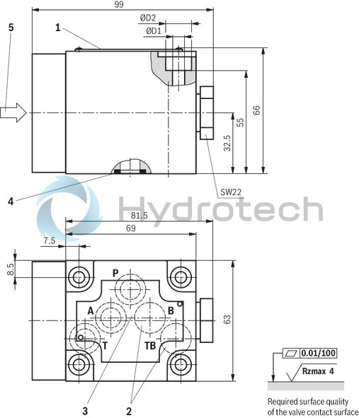
|
Operating pressure |
ØD1 |
ØD2 |
|
mm |
mm |
|
| 420 bar | 6.4 | 14 |
| 630 bar | 8.4 | 14 |
|
1 |
Name plate |
|
2 |
Attention!With 3/2 directional seat valves, ports B and TB are available as blind counterbores. |
|
3 |
Porting pattern according to DIN 24340 form A |
|
4 |
Seal rings |
|
5 |
Types of actuation |
Valve mounting screws (separate order)
420 bar version:4 hexagon socket head cap screws
ISO 4762 M6 x 65 - 10.9 - flZn - 240 h-L
(friction coefficient μtotal = 0.09 to 0.14);
tightening torque MA = 12.5 Nm ± 10 %,
material no. R913000127
630 bar version:4 hexagon socket head cap screws
ISO 4762 M8 x 65 - 10.9 - flZn - 240 h-L
(friction coefficient μtotal = 0.09 to 0.14);
tightening torque MA = 30 Nm ± 10 %,
material no. R913000368
4/2 directional seat valve – NG10
Dimensions in mm
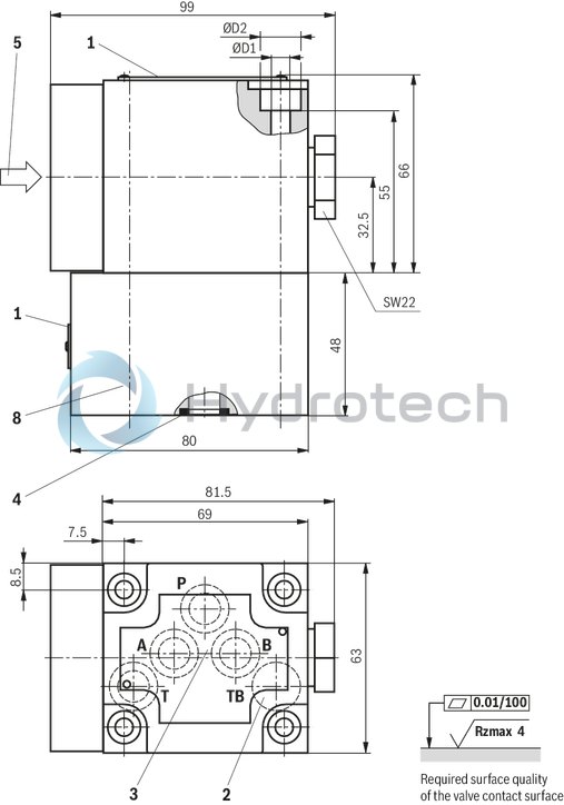
|
Operating pressure |
ØD1 |
ØD2 |
|
mm |
mm |
|
| 420 bar | 6.4 | 14 |
| 630 bar | 8.5 | 14 |
|
1 |
Name plate |
|
2 |
Attention!With 4/2 directional seat valves, port TB is available as blind counterbore. |
|
3 |
Porting pattern according to DIN 24340 form A |
|
4 |
Seal rings |
|
5 |
Types of actuation |
|
8 |
Plus-1 plate |
Valve mounting screws (included in the scope of delivery)
420 bar version:4 hexagon socket head cap screws
ISO 4762 M6 x 115 - 10.9 - flZn - 240 h-L
(friction coefficient μtotal = 0.09 to 0.14);
tightening torque MA = 12.5 Nm ± 10 %,
material no. R900018811
630 bar version:4 hexagon socket head cap screws
ISO 4762 M8 x 115 - 10.9 - flZn - 240 h-L
(friction coefficient μtotal = 0.09 to 0.14);
tightening torque MA = 30 Nm ± 10 %,
material no. R913000368
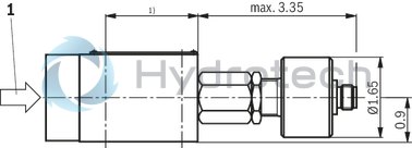
Operating methods
Type M-.SMR…
Dimensions in mm

|
1 |
Idle stroke |
|
2 |
Working stroke |
|
3 |
Excessive stroke |
|
4 |
Roller width 6 mm |
|
5 |
Actuating angle in both directions |
Spool position monitoring
Dimensions in mm
Inductive position switch type QM
Dimensions in mm

| 1) | For dimensions, see valve dimensions |
|
1 |
For the operating method, please refer to features and dimensions |
Notice:
The dimensions are nominal dimensions which are subject to tolerances.
Seat valves can be used according to the spool symbols as well as the assigned operating pressures and volume flows (see performance limits).
In order to ensure a safe functioning, it is absolutely necessary to observe the following:
In order to switch the valve safely and/or maintain it in its spool position, the pressure must be pP ≥ pA ≥ pT (for design reasons). Seat valves have a negative spool overlap, i.e. leakage oil occurs during the switching process. However, this process takes place within such a short time that it is irrelevant in nearly all cases of use. The indicated maximum flow must not be exceeded (if applicable, use a throttle insert for flow limitation)!Plus-1 plate:
When using the Plus-1 plate (4/2 directional function), the following lower operating values are to be observed: pmin = 8 bar ; qV > 3 l/min . The ports P, A, B and T are clearly specified according to their tasks. They must not be arbitrarily exchanged or closed! With 3- and 4-way switching position, port T must always be connected. The flow is only admissible in the direction of arrow!