


BOSCH REXROTH
R901363576
$4,571.28 USD
- BOSCH REXROTH
- Material:R901363576
- Model:LFA40DB2-7X/110FE
Quantity in stock: 0
The Bosch Rexroth LFA40DB2-7X/110FE (R901363576) is a high-quality pressure relief valve designed for subplate mounting in hydraulic systems. This valve is part of the LFA series and is a pilot-operated, 3-way cartridge valve in seat design, ensuring reliable performance for controlling hydraulic flow and pressure. The model features manual pressure adjustment capabilities, allowing users to set the maximum pressure with precision. It has been Typeexamination tested and complies with the Pressure Equipment Directive EU, signifying its adherence to stringent safety standards. This specific model comes with a hexagon type control cover which facilitates easy manual adjustments of the maximum pressure. It can handle a maximum operating pressure of up to 350 bar and offers various response pressures within this range. The valve is suitable for a wide range of hydraulic fluids including HL, HLP, HLPD, HVLP, HVLPD, HETG, HEES, HEPG, HFDU, and HFDR types. The construction of this valve includes a factory nozzle fitting and an installed compression spring that must remain unaltered to maintain the integrity of the device. The LFA40DB2-7X/110FE ensures operational safety by preventing internal leakage from the spring chamber to port B through its robust piston sealing. For additional convenience and functionality, this model provides an optional rotary knob alongside the standard hexagon adjustment type. This feature allows for quick manual reduction of pressure adjustment without affecting the set relief pressure setting—ideal for regular functional testing. The Bosch Rexroth LFA40DB2-7X/110FE valve is designed for easy installation with an installation bore according to ISO standard. Its size and component series are optimized for efficient operation with a maximum flow rate specified by the manufacturer's standards. This model ensures high performance in hydraulic applications where precise pressure limitation is critical.
Size 40, manual maximum pressure adjustment
Control cover for 2-way cartridge valves, reliable limiting of the pressure in connection with a 2-way cartridge valve according to the hydraulic symbol.
Unpacked Weight: 10.001 kg
General
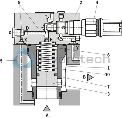
Type-examination tested safety valves type LFA . DB…E according to Pressure Equipment Directive 2014/68/EU are pilot-operated 2-way cartridge valves in seat design with set relief pressure setting pmax.
The complete valve generally consists of one cartridge valve (1) for installation bores according to ISO 7368 and one respective control cover (2) with integrated sealed pressure limitation unit (4).
The factory nozzle fitting (9) ("X", "F") as well as the installed compression spring (10) must not be changed.
The installation position ("D") is not fitted. The cartridge valve (1) is designed as seat valve without area difference. The relief pressure effective at port A is directed to the spring chamber (6) of the cartridge valve (1) and to the pressure limitation unit (4) via channel X (5). The piston sealing (7) prevents an internal leakage from the spring chamber (6) to port B and thus increases the operational safety by avoiding gap filtration. Under the pressure value set at the pressure limitation unit (4), the spool (3) is pressure-compensated and remains closed in a seat-tight manner due to the spring force of the compression spring (10). The pressure equilibrium at the spool (3) is only changed when the relief pressure at port A is reached, namely by opening the pressure limitation unit (4), so that excessive hydraulic fluid directly flows to
channel B via the spool (3) and the pressure in A is limited to the set pressure value.
The pressure limitation unit (4) is optionally available with rotary knob. This allows for a manual reduction of the pressure adjustment without changing the relief pressure setting. This simplifies a regular functional test.
| Hexagon |
| Type-examination tested |
| Size 32 … 63 |
| Maximum operating pressure 420 bar |
| Maximum flow 5000 l/min |
| Type-examination tested safety valves according to Pressure Equipment Directive 2014/68/EU |
| Component series 7X |
| Data Sheet | Download Data Sheet |
| Manual | Download Manual |
| Manual | Download Manual |
| Manual | Download Manual |
| Max. pressure | 400 |
| Productgroup ID | 9,10,11,12,13,14 |
| Type of actuation | manual pressure adjustment |
| Size | 40 |
| Type of connection | Subplate mounting |
| Weight | 10.001 |
| Seals | FKM |
| Hydraulic fluid | HL,HLP,HLPD,HVLP,HVLPD,HETG,HEES,HEPG,HFDU,HFDR |
|
01 |
02 |
03 |
04 |
05 |
06 |
07 |
08 |
||
|
LFA |
DB |
– |
7X |
/ |
E |
|
01 |
Control cover |
LFA |
|
02 |
Size 40 |
40 |
|
Size 50 |
50 |
|
|
Size 63 |
63 |
|
|
03 |
Pressure relief function |
DB |
|
Adjustment types |
||
|
04 |
Rotary knob |
1 |
|
Hexagon |
2 |
|
|
05 |
Component series 70 ... 79 (70 ... 79: unchanged installation and connection dimensions) |
7X |
|
Response pressure (50 … 400 bar, in steps of 10 bar, for maximum flow, see below) |
||
|
06 |
50 bar |
050 |
|
60 bar |
060 |
|
|
…bar |
… |
|
|
400 bar |
400 |
|
|
Seal material |
||
|
07 |
NBR seals |
N |
|
FKM seals |
F |
|
|
Observe compatibility of seals with hydraulic fluid used. |
||
|
08 |
Type-examination tested safety valve according to Pressure Equipment Directive 2014/68/EU |
E |
|
Size |
Component marking |
Maximum flowqVmax in l/min "Q" |
Response pressure p in bar "p" |
|
|
Mineral oils: HL, HLP |
Other approved hydraulic fluids (see "Technical data") |
|||
|
40 |
TÜV.SV.▢‒1138.38.F.Q.p |
900 |
800 |
50 … 90 |
|
1500 |
1350 |
100 … 190 |
||
|
2000 |
1800 |
200 … 290 |
||
|
2400 |
2150 |
300 … 400 |
||
|
50 |
TÜV.SV.▢‒1138.48.F.Q.p |
1400 |
1400 |
50 … 90 |
|
2000 |
2000 |
100 … 190 |
||
|
2600 |
2600 |
200 … 290 |
||
|
3600 |
3600 |
300 … 400 |
||
|
63 |
TÜV.SV.▢‒1138.61.F.Q.p |
1750 |
1550 |
50 … 90 |
|
2500 |
2250 |
100 … 190 |
||
|
3600 |
3600 |
200 … 290 |
||
|
5000 |
5000 |
300 … 400 |
||
▢ Information is entered at the factory
Order example:
qV = 2200 l/min, p = 270 bar
→ Type LFA 50 DB.‒7X/270.E
→ TÜV.SV.▢‒1138.48.F.2600.270
general
|
Size |
40 | 50 | 63 | |
|
Ambient temperature range |
°C |
-10 … +80 | ||
hydraulic
|
Size |
40 | 50 | 63 | ||
|
Maximum operating pressure |
Port B |
bar |
15 | ||
|
Port T |
depressurized to the tank | ||||
|
Port Y |
depressurized to the tank | ||||
|
Maximum response pressure |
Port A |
bar |
400 | ||
|
Port X |
bar |
400 | |||
|
Maximum flow 1) |
Port A to B |
l/min |
2400 | 3600 | 5000 |
|
Maximum pilot flow |
Port Y |
l/min |
4 | 15 | 23 |
|
Port T |
l/min |
4 | 15 | 23 | |
|
Hydraulic fluid |
see table below | ||||
|
Hydraulic fluid temperature range |
°C |
-10 … +60 | |||
|
Viscosity range |
mm²/s |
12 … 230 | |||
|
Maximum admissible degree of contamination of the hydraulic fluid, cleanliness class according to ISO 4406 (c) 2) |
Class 20/18/15 | ||||
| 1) | With mineral oil |
| 2) | The cleanliness classes specified for the components must be adhered to in hydraulic systems. Effective filtration prevents faults and simultaneously increases the life cycle of the components. For the selection of the filters, see www.boschrexroth.com/filter. |
|
Hydraulic fluid |
Classification |
Suitable sealing materials |
Standards |
Data sheet |
|
|
Mineral oils |
HL, HLP |
NBR, FKM |
DIN 51524 |
90220 |
|
|
Bio-degradable |
Insoluble in water |
HETG |
FKM |
ISO 15380 |
90221 |
|
HEES |
FKM |
||||
|
Soluble in water |
HEPG |
FKM |
ISO 15380 |
||
|
Flame-resistant |
Water-free |
HFDU (glycol base) |
FKM |
ISO 12922 |
90222 |
|
HFDU (ester base) |
FKM |
||||
|
HFDR |
FKM |
||||
|
Containing water |
HFC (Fuchs Hydrotherm 46M, Petrofer Ultra Safe 620) |
NBR |
ISO 12922 |
90223 |
|
|
Important information on hydraulic fluids: For more information and data on the use of other hydraulicfluids, please refer to the data sheets above or contact us. There may be limitations regarding the technical valve data (temperature, pressure range, life cycle, maintenance intervals, etc.). Flame-resistant - containing water: Life cycle as compared to operation with mineral oil HL, HLP 30 … 100%. Bio-degradable and flame-resistant: If this hydraulic fluid is used, small amounts of dissolved zinc may get into the hydraulic system. |
|||||
For applications outside these parameters, please consult us!
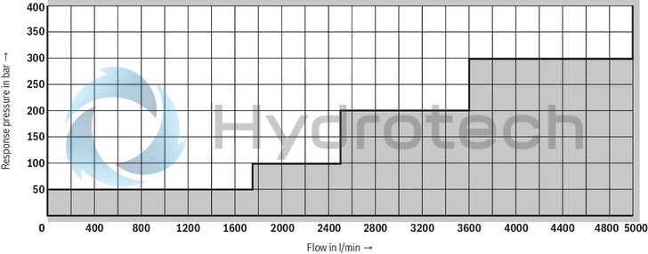
Admissible flow ranges – size 40
Mineral oil
(measured with HLP46, ϑOil = 40 ±5 °C)
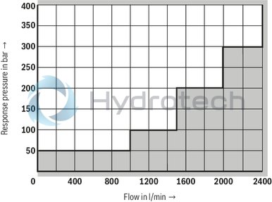
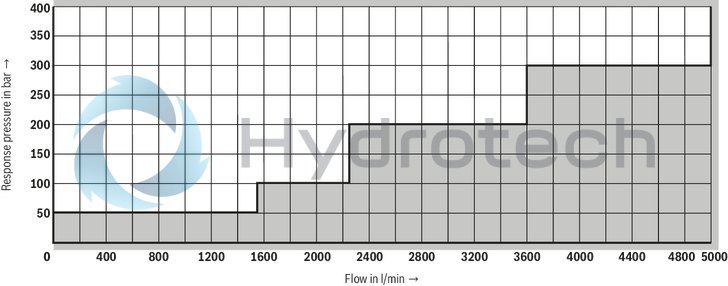
Other approved hydraulic fluids (see "Technical data")
(simulated; kinetic viscosity 40 mm²/s)
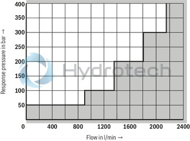
Admissible flow ranges – size 50
Mineral oil
(measured with HLP46, ϑOil = 40 ±5 °C)

Other approved hydraulic fluids (see "Technical data")
(simulated; kinetic viscosity 40 mm²/s)
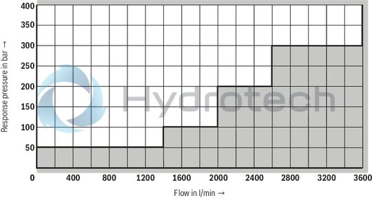
Admissible flow ranges – size 63
Mineral oil
(measured with HLP46, ϑOil = 40 ±5 °C)
Other approved hydraulic fluids (see "Technical data")
(simulated; kinetic viscosity 40 mm²/s)
Notes:
The flow values only apply for depressurized pilot oil return. Operating points in the gray areas of the characteristic curves are not admissible with this valve. Observe the admissible flows of the overall system.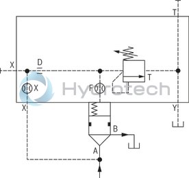
Dimensions in mm

|
1 |
Name plate |
|
2 |
Locating pin |
|
3 |
Pilot control valve, adjustment type "2" |
|
4 |
Pilot control valve, adjustment type "1" |
|
5 |
For valve mounting set, see below |
|
6 |
External connections |
|
NG |
H1 |
H2 |
H3 |
H4 |
H5 |
H6 |
▢ L1 |
L2 |
L3 |
L4 |
L5 |
D1 |
D2 |
|
mm |
mm |
mm |
mm |
mm |
mm |
mm |
mm |
mm |
mm |
mm |
|||
| 40 | 60 | 32 | 27 | 69 | 105 | 28 | 125 | 89 | 76 | 60 | 68 | G1/4 | G1/4 |
| 50 | 60 | 34 | 31 | 67 | 122 | 23 | 140 | 105 | 84 | 70 | 79 | G1/2 | G1/4 |
| 63 | 82 | 50 | 40 | 91 | 155 | 30 | 180 | 144 | 90 | 90 | 90 | G1/2 | G1/2 |
Notice:
The dimensions are nominal dimensions which are subject to tolerances.
Valve mounting set (separate order)
|
Size |
Quantity |
Comprising: |
Material number |
|
40, 50 |
4 |
Hexagon socket head cap screw ISO 4762 - M20 x 80 - 10.9-flZn/nc/480h/C (thereof 1 special screw with bore) Tightening torque MA = 480 Nm ±10 % |
R901362574 |
|
1 |
Sealing material |
||
|
63 |
4 |
Hexagon socket head cap screw ISO 4762 - M30 x 110 - 10.9-flZn/nc/480h/C (thereof 1 special screw with bore) Tightening torque MA = 1600 Nm ±10 % |
R901362575 |
|
1 |
Sealing material |
Notices:
For reasons of stability, exclusively the specified valve mounting screws may be used. The specified tightening torques were calculated with total friction coefficient μtotal = 0.09 ... 0.14; adjust in case of modified surfaces. The specified tightening torques stated are guidelines when using screws with the specified friction coefficients and when using a manual torque wrench (tolerance ± 10%).Installation bore and connection dimensions according to ISO 7368 (main pressure relief valve)
|
1 |
Depth of fit |
|
2 |
Port B can be positioned arbitrarily, radially to port A, observing the tapped holes and pilot oil bores. |
|
3 |
Bore for locating pin |
|
NG |
40 | 50 | 63 | |
|
ØD1H7 |
mm |
75 | 90 | 120 |
|
ØD2 |
mm |
40 | 50 | 63 |
|
ØD3 |
mm |
40 | 50 | 63 |
|
ØD3 max 1) |
mm |
50 | 63 | 80 |
|
ØD4H7 |
mm |
55 | 68 | 90 |
|
D5 |
M20 | M20 | M30 | |
|
ØD6 |
mm |
10 | 10 | 12 |
|
ØD7H13 |
mm |
6 | 8 | 8 |
|
H1 |
mm |
84.5 | 97.5 | 127 |
|
H2 |
mm |
105 | 122 | 155 |
|
mm |
+ 0.1 | + 0.1 | + 0.1 | |
|
H3 |
mm |
87 | 100 | 130 |
|
mm |
± 0.3 | ± 0.3 | ± 0.3 | |
|
H4 |
mm |
45 | 45 | 65 |
|
H5 |
mm |
15 | 17 | 20 |
|
H6 |
mm |
3 | 3 | 4 |
|
H7 |
mm |
30 | 35 | 40 |
|
H8 |
mm |
3 | 4 | 4 |
|
H9 |
mm |
2.5 | 2.5 | 3 |
|
L1 |
mm |
125 | 140 | 180 |
|
L2 |
mm |
85 | 100 | 125 |
|
L3 |
mm |
42.5 | 50 | 62.5 |
|
L4 |
mm |
50 | 58 | 75 |
|
L5 |
mm |
23 | 30 | 38 |
|
U |
mm |
0.05 | 0.05 | 0.05 |
|
Ro max |
mm |
4 | 4 | 4 |
|
Ru max |
mm |
1 | 1 | 1 |
| 1) | Recommendation deviating from the standard. |
Safety instructions
When selecting a type-examination tested safety valve, it must be observed that for the desired response pressure p the maximum flow possible lies below the admissible flow qVmax . According to the Pressure Equipment Directive 2014/68/EU, the increase in the system pressure due to the flow must not exceed 10 % of the set response pressure (see type key, component marking). The maximum admissible flow specified in the component marking qVmax must not be exceeded! Discharge lines of safety valves must end in a risk-free manner. Fluid must not accumulate in the discharge system (see data sheet AD2000 A2). Safety valves with adjustment type “1” (rotary knob) may only be unloaded in case of maintenance. Operation outside the specified pressure ranges is not admissible.
Always observe application notes:
The response pressure with a flow of 12 l/min and a hydraulic fluid viscosity of 46 mm2/s specified in the component marking is set by default. Within the admissible viscosity range, the response pressure may vary by +3 % (230 mm2/s) to -3 % (12 mm2/s).
The maximum flow stated in the component marking applies for applications without counter pressure in the control line (port Y). By removing the lead seal at the safety valve, the approval according to the Pressure Equipment Directive becomes void. The nozzle fittings installed at the factory as well as the main spool compression spring must not be changed. Basically, the requirements of the Pressure Equipment Directive and of data sheet AD 2000 A2 have to be observed. In order to prevent unauthorized assembly, the valve assembly can be additionally secured by means of the valve mounting set (sealing) (separate order, see “Dimensions”).