


BOSCH REXROTH
R901354307
$184.46 USD
- BOSCH REXROTH
- Material:R901354307
- Model:VT-SSBA1-PWM-1X/V002/15
Quantity in stock: 0
The Bosch Rexroth VT-SSBA1-PWM-1X/V002/15 (R901354307) is a sophisticated switching amplifier designed to enhance the performance and efficiency of standard directional valves equipped with 24V solenoids. This device is engineered to be mounted directly onto the K connector of the valve, ensuring a seamless integration into hydraulic systems. One of the primary capabilities of this switching amplifier is its ability to significantly reduce the switching time of directional valves. It achieves this by initially overexciting the solenoid with 24V for a brief period, which is then followed by a reduction in voltage. The necessary holding current is maintained through pulse width modulation (PWM), optimizing operational efficiency. In addition to its fast-switching feature, the VT-SSBA1-PWM-1X/V002/15 offers substantial energy savings. After a set power supply time and successful hydraulic valve actuation, it transitions to PWM mode, considerably lowering power consumption compared to continuous current methods. This results in holding power that is less than what would be required for a 24V valve at the same supply voltage, offering cost savings over time. The unit also includes an enable input feature that, when activated with a high signal, causes an LED status display to flash yellow, providing visual feedback on operational status. To assist users in matching their valves with this amplifier, Bosch Rexroth has included detailed technical data sections that outline both switching times and energy-saving potential for various valve configurations. The PWM functionality ensures precise control over on/off ratios at 24V, further enhancing the versatility and applicability of this device in various hydraulic applications.
The switching amplifier VT-SSBA1-PWM is directly mounted at the K4 connector of the valve.
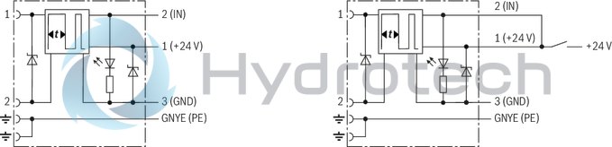
It is supplied with 24 V direct voltage. If at wire 2 (enable "IN"), a high-signal is applied, the voltage profile is applied at the valve according to the functional diagram. If the enable input is switched, the status display LED is flashing "yellow".
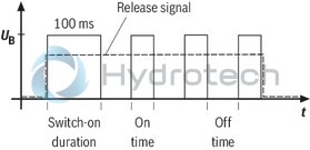
Fast switching (V001)
As fast switching amplifier, the VT-SSBA1-PWM considerably reduces the switching time of standard directional valves in connection with 12 V solenoids.
On switching on, the solenoid is overexcited with 24 V by 100 %. Afterwards, the voltage is reduced and the required holding current is set via pulse width modulation.
The switching time table in section Technical data illustrates the assignment of the valves to the switching amplifier.
Energy saving (V002)
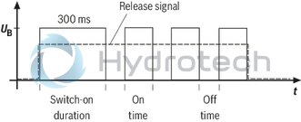
If 24 V standard directional valves are used, the switching amplifier considerably reduces the continuous current to save energy.
After a defined power supply time and the connected hydraulic switching of the valve, the system switches to pulse width modulation and the power is considerably reduced. This leads to a holding power under the power of a 24 V valve at 24 V supply voltage.
The table on energy saving in section Technical data illustrates the assignment of the valves to the switching amplifier.
PWM at V002: on/off ratio = 60/40
|
01 |
Connector switching amplifier with pulse width modulation (PWM) |
VT-SSBA1-PWM |
|
02 |
Component series 10 ... 19 (10 ... 19: unchanged installation and connection dimensions) |
1X |
|
03 |
Quick switching of valves with 12 V solenoids |
V001 |
|
Energy saving by power reduction at valves with 24 V solenoids |
V002 |
|
|
04 |
Cable length 5 m |
5 |
|
Cable length 10 m |
10 |
|
|
Cable length 15 m |
15 |
|
|
05 |
Further details in the plain text |
* |
|
01 |
02 |
03 |
04 |
05 |
|||
|
VT-SSBA1-PWM |
‒ |
1X |
/ |
/ |
* |
General
|
Type / version |
VT-SSBA1-PWM-1X/V001 | VT-SSBA1-PWM-1X/V002 | |
|
Component series |
1X | ||
|
Design |
Plug-in connector | ||
Electric
|
Type / version |
VT-SSBA1-PWM-1X/V001 | VT-SSBA1-PWM-1X/V002 | |||
|
Operating voltage |
nominal |
U |
V |
24 | |
|
Lower limit value |
UB(t)min |
V |
21.6 | ||
|
Upper limit value |
UB(t)max |
V |
26.4 | ||
|
Control voltage |
ON |
U |
V |
10…30 (I = 2.5…12 mA) | |
|
OFF |
U |
V |
<3.5 | ||
|
Clock frequency PWM switching amplifier |
f |
PWM operation 300…500 Hz | |||
|
Switch-on pulse duration |
t |
ms |
100…115 | 300…330 | |
|
PWM duty factor |
t |
% |
40 ±5 on | 60 ±5 on | |
|
Holding current |
Imax |
A |
2 | ||
Sonstige Angaben
|
Type / version |
VT-SSBA1-PWM-1X/V001 | VT-SSBA1-PWM-1X/V002 | |||
|
Connection to the solenoid |
Standard |
EN 175301-803 | |||
|
Connection cross-section |
S |
4 x 0.75 mm2 | |||
|
Anschlussart |
Potted-in cable with open end, jacket: PUR-JZ black, wire insulation: PP black, green/yellow | Potted-in cable with open end | |||
|
Cable diameter |
d |
mm |
6.5 | ||
|
Protection class according to DIN EN 60529 |
IP 65/IP 67 | ||||
|
Conformity |
According to EMC directive 2004/108/EG applied harmonized standards: EN 61000-6-2:2005, EN 61000-6-3:2007 | ||||
|
Ambient temperature range |
ϑ |
°C |
-20 … 60 | ||
|
Storage temperature range |
ϑ |
°C |
-20 … 60 | ||
|
Weight |
m |
g |
350 | ||
For applications outside these parameters, please consult us!
Switching times (with variant V001)
Comparison of 24 V coil (control standard 24 V signal) with 12 V coil (control viaVT-SSBA1-PWM-1X/V001…)
Additional valves on request.
If the connector switching amplifier is used, the power limit may be improved. The degree of improvement depends on the respective switching symbol of the valve.
Additional information on request.
Notice:
The specified switching times correspond to the time of signaling until a pressure change of 5 %. The switching times are specified for the same power limits as documented in data sheets 23178, 23340 and 23352 and for a horizontal installation position. The use of plug-in amplifiers V001 is not possible in connection with valves with amplified spring.|
Switching times for 5-4WE10…5X valves (5 chamber) |
Switching times for Z-4WE6…3X valves |
|||||||
|
Control spool |
Coil |
Switching time in ms |
Control spool |
Coil |
Switching time in ms |
|||
|
ON |
OFF |
ON |
OFF |
|||||
|
J2 |
24 V |
170 |
23 |
E63 |
24 V |
27 |
14 |
|
|
12 V at V001 |
44 |
12 V at V001 |
15 |
|||||
|
X84 |
24 V |
39 |
67 |
E68 |
24 V |
27 |
14 |
|
|
12 V at V001 |
20 |
12 V at V001 |
15 |
|||||
|
X250 |
24 V |
31 |
20 |
|||||
|
12 V at V001 |
16 |
|||||||
|
X252 |
24 V |
47 |
13 |
|||||
|
12 V at V001 |
17 |
|||||||
|
Switching times for 4WE10…5X valves (3 chamber) |
Switching times for 4WE6…6X valves |
|||||||
|
Control spool |
Coil |
Switching time in ms |
Control spool |
Coil |
Switching time in ms |
|||
|
ON |
OFF |
ON |
OFF |
|||||
|
C |
24 V |
58 |
48 |
C |
24 V |
27 |
14 |
|
|
12 V at V001 |
26 |
12 V at V001 |
17 |
|||||
|
D |
24 V |
78 |
28 |
D |
24 V |
42 |
11 |
|
|
12 V at V001 |
29 |
12 V at V001 |
25 |
|||||
|
E |
24 V |
55 |
35 |
E |
24 V |
32 |
11 |
|
|
12 V at V001 |
22 |
12 V at V001 |
22 |
|||||
|
E67 |
24 V |
84 |
31 |
E67 |
24 V |
39 |
12 |
|
|
12 V at V001 |
24 |
12 V at V001 |
21 |
|||||
|
J |
24 V |
63 |
51 |
G |
24 V |
33 |
11 |
|
|
12 V at V001 |
28 |
12 V at V001 |
28 |
|||||
|
J2 |
24 V |
47 |
31 |
J |
24 V |
37 |
17 |
|
|
12 V at V001 |
24 |
12 V at V001 |
17 |
|||||
|
Y |
24 V |
57 |
31 |
L |
24 V |
36 |
15 |
|
|
12 V at V001 |
23 |
12 V at V001 |
21 |
|||||
|
Y11 |
24 V |
46 |
50 |
M |
24 V |
47 |
26 |
|
|
12 V at V001 |
28 |
12 V at V001 |
33 |
|||||
|
X7 |
24 V |
62 |
13 |
|||||
|
12 V at V001 |
47 |
|||||||
Notice:
The use of plug-in amplifiers V002 is not possible in connection with valves with amplified spring. Reduction of the coil temperature by at least 30 KEnergy saving (with variant V002)
Energy saving with valves with 24 V coils using plug-in amplifier VT-SSBA1-PWM-1X/V002…
|
5-.WE (5-chamber version) |
Power consumption for Z-4WE6…3X valves |
|||||
|
Control spool |
Power in W at 24 V coil |
Power in W at 24 V coil with V002 |
Control spool |
Power in W at 24 V coil |
Power in W at 24 V coil with V002 |
|
|
J2 |
30 |
18 |
E63 |
30 |
18 |
|
|
X84 |
E68 |
|||||
|
X250 |
||||||
|
X252 |
||||||
|
Power consumption for 4WE10…5X valves (3 chamber) |
Power consumption for 4WE6…6X valves |
|||||
|
Control spool |
Power in W at 24 V coil |
Power in W at 24 V coil with V002 |
Control spool |
Power in W at 24 V coil |
Power in W at 24 V coil with V002 |
|
|
C |
40 |
24 |
C |
30 |
18 |
|
|
D |
D |
|||||
|
E |
E |
|||||
|
E67 |
E67 |
|||||
|
J |
G |
|||||
|
J2 |
J |
|||||
|
Y |
L |
|||||
|
Y11 |
M |
|||||
|
X7 |
||||||
Wire 2: enable "IN"
Wire 1: Operating voltage "+UB" (+24 V)
Wire 3: Operating voltage "GND"
Wire GNYE: Protective earth "PE"
4/2-way version
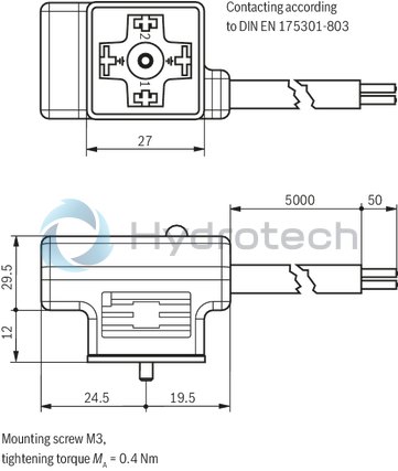
Dimensions in mm
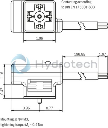
Dimensions in mm
The connector switching amplifier may only operated in accordance with the limits and applications defined in the data sheet. Sufficient distance to radios and mobile phones is required (>> 1 m). In case of overload or short-circuit, the output is de-energized. Before switching it on again, enable signal "IN" has to be switched at "ON" (< 3.5 V). There is no galvanic isolation between the input and output. If used as power reducer, the power in PWM operation is not sufficient for repeated switching of the valve after exceeding the power limit in switched state. In case of an error, the temperature of the valve solenoid may increase. Take external monitoring measures to ensure that the maximum admissible surface temperature of the solenoid is complied with. The VT-SSBA1-PWM is no safety-relevant part of a control system according to EN ISO 13849-1:2006. To comply with safety requirements, the following points must be observed: In case the safety function is required, the voltage supply and the enable input of the VT-SSBA1-PWM is to be switched off by a suitable switching element with appropriate reliability. If persons have to enter the danger zone with activated VT-SSBA1-PWM, additional measures for guaranteeing their safety have to be taken for the reasons specified above.