

BOSCH REXROTH
R901347341
$4,300.13 USD
- BOSCH REXROTH
- Material:R901347341
- Model:DBETA-6X/P500G24K31A1M
Quantity in stock: 0
The Bosch Rexroth DBETA-6X/P500G24K31A1M (R901347341) is a direct actuated proportional pressure relief valve designed for high-performance hydraulic systems requiring reliable pressure limitation. This valve is tailored to maintain system pressure within specific limits by converting an electrical command signal into a proportional hydraulic force. It features integrated electronics, allowing for precise control and adjustment of the pressure setpoint. With a maximum operating pressure of 500 bar and the ability to handle a maximum flow of 6 liters per minute, this valve is well-suited for applications that demand accurate and stable pressure regulation. The electrical actuation with integrated electronics enables smooth and continuous adjustment of the system pressure, providing users with enhanced control over their hydraulic systems. The DBETA-6X/P500G24K31A1M comes with an integrated pressure sensor, which captures real-time data that can be read via an analog output. This feature ensures immediate feedback on the system's performance, enhancing monitoring capabilities. The pressure controller can be adjusted to suit various applications simply by using the on-board DIL switch, facilitating easy customization to meet specific requirements. Designed for subplate mounting with a porting pattern according to ISO standards, this valve offers straightforward installation and compatibility with existing systems. It boasts a linear command value-pressure characteristic curve and virtually flow-independent pressure control, ensuring consistent operation across different flow rates. The robust design includes NBR seals compatible with hydraulic fluids such as HL, HLP, HLPD, HVLP, HVLPD, and HFC. With its CE conformity in accordance with EMC directive 2004/108/EC, users can expect reliable performance that meets stringent European standards. The size 6 component series X valve is engineered to deliver precise control in demanding industrial environments where accurate pressure management is critical.
Size 6, P → T, electrical with integrated electronics, 24 V DC
Industrial hydraulic valve in a high performance range. Reliable limitation of the pressure to the command value signal.
Unpacked Weight: 1.880 kg
General information
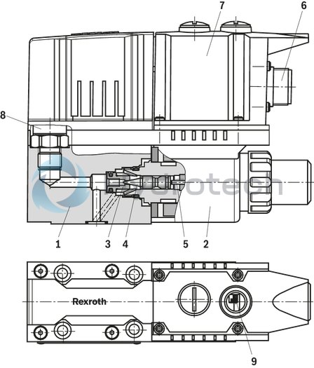
Proportional pressure relief valves of type DBETA are used for system pressure limitation. Operation is effected by means of proportional solenoid. The pressure is regulated by the pressure sensor and the valve electronics. Dependent on the electric command value, these valves can be used to steplessly set and adjust the system pressure to be limited. The valves mainly consist of the housing (1), the valve seat (3), the valve poppet (4), the proportional solenoid (2), the integrated electronics (7) and the pressure sensor (8).
Basic principle
The supply voltage and the command value are applied to the connector (6). Dependent on the command value, the electronics convert the input signal into current. The proportional solenoid converts the electric current into mechanical force that acts on the valve poppet (4) via the armature plunger (5). The valve poppet (4) counteracts the hydraulic force in channel P. When the hydraulic force at the valve poppet (4) equals the solenoid force, the set pressure is reached. By increasing/reducing cross-section P to T, the pressure is maintained at the set level. The pressure sensor (8) captures the pressure in channel P and/or B and the integrated electronics (7) regulate the pressure independently of the flow. Connector (6) provides the pressure in channel P and/or B as an analog actual value (0 to 10 V and/or 4 to 20 mA). If the command value is zero, the control electronics only applies the minimum control current to the proportional solenoid (2) and the minimum set pressure is applied. With the DIL switch (9) the integrated pressure controller can be adjusted to various applications.
| Integrated pressure sensor |
| Direct actuated |
| Pressure rating 500 bar |
| Proportional pressure valve in poppet seat design |
| Component series 6X |
| Size 6 |
| Maximum operating pressure 500 bar |
| Maximum flow 5 l/min |
| Data Sheet | Download Data Sheet |
| Manual | Download Manual |
| Manual | Download Manual |
| Manual | Download Manual |
| Spool symbol | P → T |
| Max. pressure | 500 |
| Electrical connection description | Connector 7-pole (6 + PE) according to EN 175201-804 |
| Productgroup ID | 9,10,11,12,13,14 |
| Number of ports | 2 |
| Type of actuation | Electrical with integrated electronics |
| Size | 6 |
| Electrical connector | Connector 7-pole (6 + PE) |
| Max. flow | 5 |
| Type of connection | Subplate mounting |
| Connection diagram NFPA | NFPA T3.5.1 R2-2002 D03 |
| Size_CETOP | D03 |
| Connection diagram | ISO 4401-03-02-0-05 |
| Supply voltage | 24 VDC |
| Number of switching positions | 2 |
| Weight | 1.880 |
| Seals | NBR |
| Hydraulic fluid | HL,HLP,HLPD,HVLP,HVLPD,HFC |
|
01 |
02 |
03 |
04 |
05 |
06 |
07 |
08 |
09 |
||
|
DBETA |
‒ |
6X |
/ |
P |
G24 |
K31 |
* |
|
01 |
Proportional pressure relief valve, pressure-controlled with integrated electronics (OBE) |
DBETA |
|
02 |
Component series 60 … 69 (60 … 69: unchanged installation and connection dimensions) |
6X |
|
03 |
Pressure measurement in channel P |
P |
|
Maximum set pressure |
||
|
04 |
Up to 50 bar |
50 |
|
Up to 100 bar |
100 |
|
|
Up to 200 bar |
200 |
|
|
Up to 350 bar |
350 |
|
|
Up to 500 bar (only possible in version "M") |
500 |
|
|
Supply voltage of the integrated electronics (OBE) |
||
|
05 |
Direct voltage 24 V |
G24 |
|
Electrical connection |
||
|
06 |
Connector DIN EN 175201-804 |
K31 |
|
Electrical interface |
||
|
07 |
Command value 0 … 10 V |
A1 |
|
Command value 4 to 20 mA |
F1 |
|
|
Seal material |
||
|
08 |
NBR seals |
M |
|
FKM seals |
V |
|
|
Observe compatibility of seals with hydraulic fluid used. (Other seals upon request) |
||
|
09 |
Further details in the plain text |
* |
For applications outside these parameters, please consult us!
general
|
Type |
DBETA | |
|
Size |
6 | |
|
Component series |
6X | |
|
Weight |
kg |
1.9 |
|
Installation position |
any | |
|
Ambient temperature range |
°C |
-20 … +60 |
|
Sine test according to DIN EN 60068-2-6 |
10...2000...10 Hz / maximum 10 g / 10 cycles | |
|
Noise test according to DIN EN 60068-2-64 |
20...2000 Hz / 10g RMS / 30 g Peak / 24 h | |
|
Shock test according to DIN EN 60068-2-27 |
15 g / 11 ms | |
|
Maximum relative humidity 1) |
% |
97 |
| 1) | with 25 to 55°C |
hydraulic
|
Type |
DBETA | |||
|
Maximum operating pressure 1) |
Port P |
Pressure rating 100 bar |
bar |
300 |
|
Port P |
Pressure rating 50 bar |
bar |
125 | |
|
Port P, A, B |
Pressure ratings 200, 350 and 500 bar |
bar |
500 | |
|
Return flow pressure |
Port T |
ideally at zero pressure to the tank | ||
|
Maximum set pressure |
Pressure rating 50 bar |
bar |
50 | |
|
Pressure rating 100 bar |
bar |
100 | ||
|
Pressure rating 200 bar |
bar |
200 | ||
|
Pressure rating 315 bar |
bar |
350 | ||
|
Pressure rating 350 bar |
bar |
500 | ||
|
Minimum set pressure 2) |
at a command value of 0 |
See characteristic curves | ||
|
Maximum flow 3) |
l/min |
5 | ||
|
Minimum line volume |
cm³ |
20 | ||
|
Hydraulic fluid |
see table | |||
|
Hydraulic fluid temperature range |
FKM seals |
°C |
-15 … +80 | |
|
NBR seals |
°C |
-20 … +80 | ||
|
Viscosity range |
mm²/s |
20 … 380 | ||
|
preferably |
mm²/s |
30 … 46 | ||
|
Maximum admissible degree of contamination of the hydraulic fluid, cleanliness class according to ISO 4406 (c) 4) |
Class 20/18/15 according to ISO 4406 (c) | |||
|
Hysteresis 5) |
% |
< 1 | ||
|
Range of inversion 5) |
% |
< 0.25 | ||
|
Response sensitivity 5) |
% |
< 0.25 | ||
|
Linearity 5) |
% |
± 1 | ||
|
Step response |
10% → 90% 6) |
ms |
165 | |
|
90% → 10% 6) |
ms |
88 | ||
| 1) | The summated pressure of all ports must not exceed 1030 bar, e. g. port P 500 bar + port B 500 bar + port T 30 bar + port A 0 bar = 1030 bar. |
| 2) | at command value 0 V or 4 mA |
| 3) | Required operating range Q > 0.5 l/min |
| 4) | The cleanliness classes specified for the components must be adhered to in hydraulic systems. Effective filtration prevents faults and simultaneously increases the life cycle of the components. For the selection of the filters, see www.boschrexroth.com/filter. |
| 5) | Of the maximum set pressure |
| 6) | Line volume < 20 cm3; qV = 0.8 l/min; depending on the system |
|
Hydraulic fluid |
Classification |
Suitable sealing materials |
Standards |
|
Mineral oils and related hydrocarbons |
HL, HLP |
NBR / FKM |
DIN 51524 |
|
Bio-degradable - insoluble in water |
HEES |
FKM |
VDMA 24568 |
|
Flame-resistant - water-free |
HFDU |
FKM |
ISO 12922 |
|
Flame-resistant - containing water |
HFC (Fuchs HYDROTHERM 46M, Petrofer Ultra Safe 620) |
NBR |
ISO 12922 |
|
Important information on hydraulic fluids: For more information and data on the use of other hydraulic fluids please contact us. There may be limitations regarding the technical valve data (temperature, pressure range, life cycle, maintenance intervals, etc.). The flash point of the process and operating medium used must be 40 K over the maximum solenoid surface temperature.
Flame-resistant - containing water: Bio-degradable: When using hydraulic fluids that are simultaneously zinc-solving, zinc may accumulate (700 mg zinc per pole tube). |
|||
|
Hydraulic fluid |
Classification |
Suitable sealing materials |
Standards |
|
Mineral oils and related hydrocarbons |
HL, HLP |
NBR / FKM |
DIN 51524 |
|
Bio-degradable - insoluble in water |
HEES |
FKM |
VDMA 24568 |
|
Flame-resistant - water-free |
HFDU |
FKM |
ISO 12922 |
|
Flame-resistant - containing water |
HFC (Fuchs HYDROTHERM 46M, Petrofer Ultra Safe 620) |
NBR |
ISO 12922 |
|
Important information on hydraulic fluids: For more information and data on the use of other hydraulic fluids please contact us. There may be limitations regarding the technical valve data (temperature, pressure range, life cycle, maintenance intervals, etc.). The flash point of the process and operating medium used must be 40 K over the maximum solenoid surface temperature.
Flame-resistant - containing water: Bio-degradable: When using hydraulic fluids that are simultaneously zinc-solving, zinc may accumulate (700 mg zinc per pole tube). |
|||
electrical
|
Type |
DBETA | ||
|
Maximum solenoid current |
A |
1.6 | |
|
Duty cycle |
% |
100 | |
|
Protection class according to DIN EN 60529 |
IP65 (with mating connector mounted and locked) | ||
|
Power supply |
V |
24 | |
|
Supply voltage range |
V |
18 … 36 | |
|
Current consumption |
A |
2 | |
|
Required fuse protection |
2 A, time-lag | ||
|
Command value input |
Voltage |
V |
0 … 10 |
|
Current |
mA |
4 … 10 | |
|
Actual value output |
Voltage |
V |
0 … 10 |
|
Current |
mA |
4 … 20 | |
(measured with HLP46, ϑOil = 40 ±5 °C)
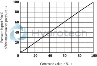
Pressure in port P dependent on the command value (flow = 0.8 l/min)
Minimum set pressure in port P dependent on the flow (command value 0 V and/or 4 mA; return flow pressure = 0 bar)
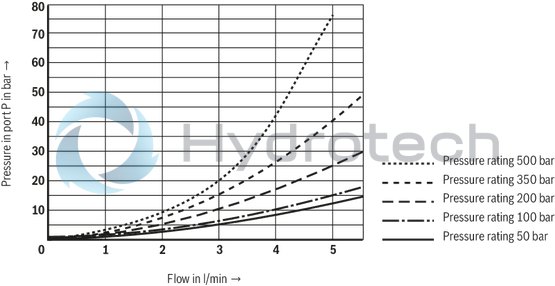
Pressure in port P dependent on the flow (applies to all pressure ratings)

Version P

|
Pin assignment |
Contact |
Assignment interface "A1" |
Assignment interface "F1" |
|
Power supply |
A |
24 VDC (u(t) = 18... 36 V); Imax ≤ 2,0 A |
|
|
B |
0 V |
||
|
Reference potential actual value |
C |
Reference potential for contact F; |
Reference contact F |
|
Differential amplifier input (command value) |
D |
0 ... + 10 V; Re > 100 kΩ |
4 ... 20 mA; Re = 100 kΩ |
|
E |
Reference potential command value |
||
|
Actual pressure value |
F |
0 ... + 10 V actual value; Imax = 5 mA |
4 ... 20 mA; load resistance maximum 600 Ω |
|
PE |
connected to solenoid and valve housing |
||
Connection cable
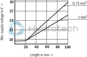
| 1) | Connection cable:- Recommendation 6-wire, 0.75 or 1mm2 plus protective earthing conductor and screening- Connect screening to PE on supply side only- Maximum admissible length 100 m The minimum supply voltage at the power supply unit depends on the length of the supply line (see diagram) |
| 2) | To comply with the requirements of the EMC directive 2004/108/EC, the metal version mating connector (R900223890) and a screened cable are required. |
Function
The electronics are supplied with voltage via ports A and B. The command value is applied to the differential amplifier ports D and E. The actual pressure value is captured by the integrated pressure sensor. The pressure command value is processed in the controller and compared to the actual pressure value. The power output stage processes the control output of the controller and controls the solenoid current. The actual pressure value is reported at port F (reference port C). With the DIL switch, the controller characteristics can be adjusted to certain applications (see "DIL switch position” table). For the system analysis, the pressure controller can be deactivated using the DIL switches. This corresponds to the function of a force-controlled pressure relief valve (DBETE).
Block diagram / pin assignment
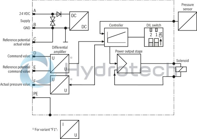
Notice:
If the pressure sensor fails, the valve switches to controlled operation. Port PIN F reports 0 V and/or 4 mA.
Notice:
If the flow changes, the pressure controller is automatically adjusted to these operating conditions. In the first cycles, this may lead to changes in the transition behavior.
DIL switch position
|
Switch (position) |
Function |
Examples of application |
|
|
2 |
1 |
||
|
off |
off |
controlled operation, no pressure control |
Commissioning / system analysis |
|
off |
on |
smallest dead volume (from 20 cm3) |
Systems with little damping |
|
on |
off |
pilot-operated, large dead volume |
Pilot valve for logic e.g. LC40 |
|
on |
on |
pilot-operated, small dead volume |
Pilot valve for logic e. g. LC16, LC25 |
|
Adjust the switch position of the application before the commissioning. Default setting: both switches to on (pilot-operated, small dead volume) |
|||
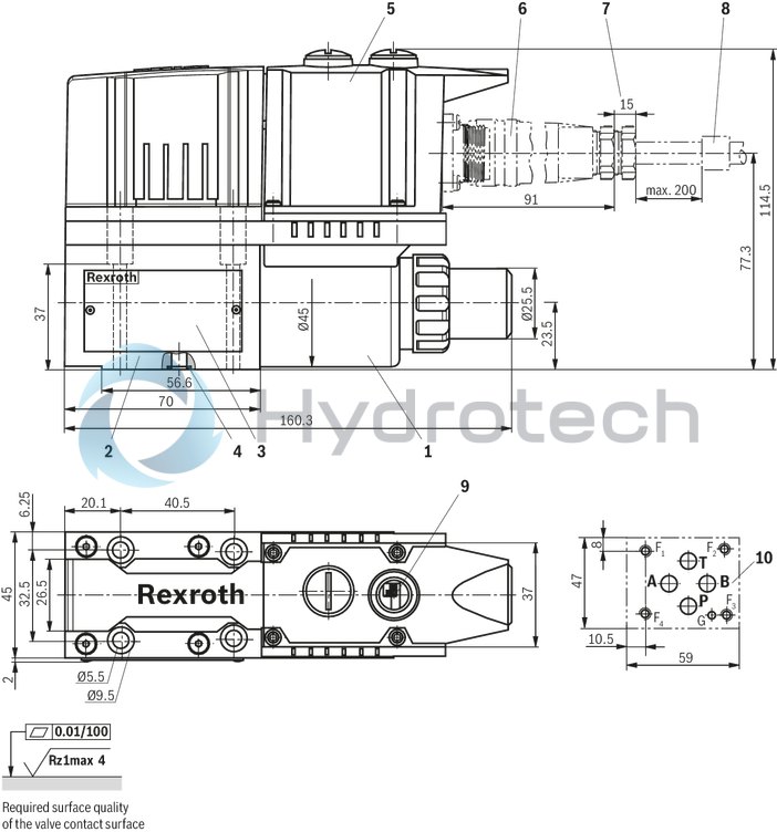
Dimensions in mm
|
1 |
Proportional solenoid |
|
2 |
Valve housing |
|
3 |
Name plate |
|
4 |
Identical seal rings for ports A, B, P, and T |
|
5 |
Integrated electronics (OBE) |
|
6 |
Mating connector |
|
7 |
Space required to remove the mating connector |
|
8 |
Cable fastening |
|
9 |
DIL switch for adjustment to various line volumes |
|
10 |
Valve connection surface, porting pattern according to ISO 4401-03-02-0-05 |
Recommended valve mounting screws (separate order):
4 hexagon socket head cap screws ISO 4762 - M5 x 45 - 10.9-flZn-240h-L
Tightening torque MA = 7 Nm ± 10%; material no. R913000140
Mating connectors for valves with round connector, 6-pole + PE
7P Z31
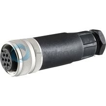
Mating connectors for valves with round connector, 6-pole + PE
7P Z31
For valves with round connector according to EN 175201-804, 6-pole + PE as well as 6-pole, compatible with VG 95328Data sheet
Spare parts & repair