
BOSCH REXROTH
R901278309
$3,445.34 USD
- BOSCH REXROTH
- Material:R901278309
- Model:DREE10-6X/315YMG24K31A1M
Quantity in stock: 0
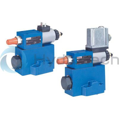
The Bosch Rexroth DREE10-6X/315YMG24K31A1M (R901278309) is a high-performance industrial hydraulic valve designed for reliable pressure reduction in accordance with the command value signal. This valve is characterized by its size B, electrical actuation with integrated electronics, and a maximum operating pressure of 315 bar. It features a spool valve that is pilot-operated with an external pilot oil return and a spool symbol B A. The electrical connection utilizes a connector pole PE in line with DIN EN standards. This model boasts a maximum flow rate and is designed for subplate mounting, conforming to the CETOP D standard and ISO connection diagrams. It operates on a supply voltage of 24 VDC and has integrated CE conformity according to EMC Directive EU. The weight of the valve is optimized for its size, and it uses NBR seals compatible with various hydraulic fluids such as HL, HLP, HLPD, HVLP, HVLPD, and HFC. The DREE10-6X/315YMG24K31A1M valve's capabilities include precise pressure control facilitated by its proportional solenoid and an optional check valve for backflow prevention between channels A and B. Additionally, it offers an optional spring-loaded pressure relief valve for maximum pressure limitation. Its design ensures good transient response characteristics while maintaining a linearized pressure-command value characteristic curve. The unit comes equipped with integrated electronics (OBE) for streamlined operation and easy implementation into various hydraulic systems where precise control of system pressure is required. The third-way port A to Y measures 0.5 mm, further demonstrating its precision capabilities. With its robust design tailored for demanding applications, this Bosch Rexroth hydraulic valve stands out as an essential component for efficient fluid power control in industrial settings.
Size 10, B → A, electrical with integrated electronics, 24 VDC
Industrial hydraulic valve in a high performance range. Reliable reduction of the pressure to the command value signal.
Unpacked Weight: 4.821 kg
Valves of type DRE(M)E are pilot-operated pressure reducing valves. They are used for operating pressure reduction.
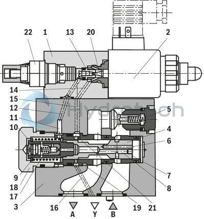
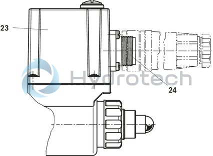
These valves basically consist of a pilot control valve (1) with proportional solenoid (2), a main valve (3) with main spool insert (4), as well as an optional check valve (5). On the proportional solenoid, there is moreover a housing (23) with the control electronics. Supply and command value voltage are applied at the connector (24). At the factory, the command value pressure characteristic curve is adjusted with little manufacturing tolerance.
Type DREE...
The pressure in channel A is set in a command value-dependent form via the proportional solenoid (2).
In rest position – no pressure in channel B –, the spring (17) holds the main spool (4) in its initial position. The connection from channel B to A is closed. A start-up jump is thereby prevented.
The pressure in channel A acts on the surface (7) of the main spool via the bore (6). The pilot oil is taken from channel B and flows through the bore (8) to the constant-current control (9) that keeps the pilot flow constant independent of the pressure drop between channel A and B. From
the constant-current control (9), the pilot flow flows in den spring chamber (10), through the bores (11) and (12) via the valve seat (13) into channel Y (14, 15, 16) and from there to the return flow. The pressure required in channel A is preset at the related amplifier. The proportional solenoid moves the valve poppet (20) in the direction of the valve seat (13) and limits the pressure in the spring chamber (10) to the set value. If the pressure in channel A is lower than the preset command value, the higher pressure in the spring chamber (10) moves the main spool to the right. The connection from B to A is opened. If the set pressure in A is reached, the forces at the main spool are balanced – the main spool is in control position.
Pressure in channel A • Spool face (7) = pressure in spring chamber (10) • Spool face – spring force (17)
If in a standing hydraulic fluid column (e. g. cylinder piston at stop), the pressure in A is to be reduced, (e. g.) a lower command value is preset at the control electronics and in this way a lower pressure is preselected which is present immediately in the spring chamber (10). The higher pressure in A which acts on the surface (7) of the main spool pushes the main spool to the stop against the plug screw (18). The connection A to B is blocked and A to Y is open. The force of the spring (17) now counteracts the hydraulic force acting on the surface (7) of the main spool. In this main spool position, the hydraulic fluid can flow from channel A via the control edge (19) to Y into the return flow.
When the pressure in A has dropped to the pressure in the spring chamber (10) plus ∆p from spring (17), the main spool closes the large control bores in the socket at the control edge A to Y.
The residual pressure differential of approx. 10 bar to the new command value pressure in A is now only unloaded via the fine control bore (21). In this way, a favorable transient response without pressure undershoot is achieved. For the free flow back from channel A to B, a check valve (5) can optionally be installed. Part of this flow from channel A simultaneously flows into the return flow via the open control edge (19) of the main spool A to Y.
Type DREME...
For hydraulic protection against an inadmissibly high electric control current at the proportional solenoid, which imperatively results in excessive pressures in port A, you can optionally install a spring-loaded pressure relief valve as maximum pressure limitation (22). The maximum pressure limitation is pre-set based on the relevant pressure rating (see table).
| Spool valve |
| Pilot-operated |
| Pilot oil return, external |
| Size 10, 25 |
| Operating pressure, max. 315 bar |
| Volume flow, max. 300 l/min |
| Component series 6X |
| Data Sheet | Download Data Sheet |
| 3D CAD | Download 3D CAD |
| Manual | Download Manual |
| Manual | Download Manual |
| Manual | Download Manual |
| Manual | Download Manual |
| Manual | Download Manual |
| Spool symbol | B → A |
| Max. pressure | 315 |
| Electrical connection description | Connector 7-pole (6 + PE) according to EN 175201-804 |
| Productgroup ID | 9,10,11,12,13,14 |
| Number of ports | 3 |
| Type of actuation | Electrical with integrated electronics |
| Conformity description | CE – according to EMC Directive 2014/30/EU |
| Size | 10 |
| Electrical connector | Connector 7-pole (6 + PE) |
| Max. flow | 300 |
| Type of connection | Subplate mounting |
| Size_CETOP | D05 |
| Connection diagram | ISO 5781 |
| Supply voltage | 24 VDC |
| Number of switching positions | 2 |
| Weight | 4.821 |
| Seals | NBR |
| Connectivity | Analog, command value 0 … 10 V |
| Hydraulic fluid | HL,HLP,HLPD,HVLP,HVLPD,HFC |
| Conformity | CE |
|
01 |
02 |
03 |
04 |
05 |
06 |
07 |
08 |
09 |
10 |
11 |
12 |
13 |
14 |
||
|
DRE |
‒ |
6X |
/ |
Y |
G24 |
K31 |
* |
|
01 |
Proportional pressure reducing valve, pilot-operated |
DRE |
|
|
02 |
Without maximum pressure limitation |
no code |
|
|
With maximum pressure limitation |
M 1) |
||
|
03 |
With integrated electronics (OBE) |
E |
|
|
04 |
Size 10 |
10 |
|
|
Size 25 |
20 |
||
|
05 |
Component series 60 … 69 (60 … 69: unchanged installation and connection dimensions) |
6X |
|
|
Pressure rating |
|||
|
06 |
50 bar |
50 |
|
|
100 bar |
100 |
||
|
200 bar |
200 |
||
|
315 bar |
315 |
||
|
07 |
Pilot oil return always external, separate and depressurized to the tank |
Y |
|
|
08 |
With check valve between A and B |
no code |
|
|
Without check valve |
M |
||
|
Supply voltage of the control electronics |
|||
|
09 |
Direct voltage 24 V |
G24 |
|
|
10 |
1600 mA version |
no code |
|
|
800 mA version |
-8 2) |
||
|
Electrical connection |
|||
|
11 |
Without mating connector, with connector according to DIN EN 175301-804, separate order |
K31 |
|
|
Electrical interface |
|||
|
12 |
Command value 0 … 10 V |
A1 |
|
|
Command value 4 to 20 mA |
F1 |
||
|
Seal material |
|||
|
13 |
NBR seals |
M |
|
|
FKM seals |
V |
||
|
14 |
Further details in the plain text |
* |
|
|
1) |
The maximum pressure limitation only serves as protection against overpressure in case of an error in the pilot valve (e. g. in case of contamination or over-current). |
||
|
2) |
Replacement for series 5X. (Attention! External amplifiers only suitable for G24 = 1.6 A solenoid), |
||
For applications outside these parameters, please consult us!
general
|
Type |
DRE(M)E | ||
|
Size |
10 | 25 | |
|
Component series |
6X | ||
|
Installation position |
Any | ||
|
Weight |
kg |
4.8 | 6.1 |
|
Storage temperature range |
°C |
-20 … +80 | |
|
Ambient temperature range |
°C |
-20 … +50 | |
hydraulic
|
Type |
DRE(M)E | |||
|
Size |
10 | 25 | ||
|
Maximum operating pressure |
bar |
315 | ||
|
Maximum operating pressure |
Port A |
bar |
315 | |
|
Port B |
bar |
315 | ||
|
Port T 1) |
separate and depressurized to the tank | |||
|
Maximum set pressure in port A |
Pressure rating 50 bar |
bar |
50 | |
|
Pressure rating 100 bar |
bar |
100 | ||
|
Pressure rating 200 bar |
bar |
200 | ||
|
Pressure rating 315 bar |
bar |
315 | ||
|
Minimum set pressure 2) |
bar |
2 | ||
|
Maximum pressure relief function |
Pressure rating 50 bar 3) |
bar |
70 | |
|
Pressure rating 100 bar |
bar |
130 | ||
|
Pressure rating 200 bar |
bar |
230 | ||
|
Pressure rating 315 bar |
bar |
350 | ||
|
Pilot flow |
l/min |
0.8 | ||
|
Maximum flow |
l/min |
200 | 300 | |
|
Hydraulic fluid temperature range |
°C |
-20 … +80 | ||
|
Viscosity range |
mm²/s |
15 … 380 | ||
|
Maximum admissible degree of contamination of the hydraulic fluid, cleanliness class according to ISO 4406 (c) 4) |
Class 20/18/15 according to ISO 4406 (c) | |||
|
Hysteresis 5) |
% |
± 3.5 | ||
|
Repetition accuracy 5) |
% |
< ± 2 | ||
|
Linearity 5) |
% |
± 2 | ||
|
Manufacturing tolerance of the command value pressure characteristic curve 6) |
% |
± 1.5 | ||
|
Step response |
10 ... 90% 7) |
ms |
≈ 130 | |
|
90 ... 10% 7) |
ms |
≈ 160 | ||
|
10 ... 90% 8) |
ms |
≈ 150 | ||
|
90 ... 10% 8) |
ms |
≈ 150 | ||
| 1) | Internal pipe Ø ≥ 5 mm; pipe length < 2500 mm |
| 2) | in channel A with command value 0 |
| 3) | set at the factory |
| 4) | The cleanliness classes specified for the components must be adhered to in hydraulic systems. Effective filtration prevents faults and simultaneously increases the life cycle of the components. For the selection of the filters, see www.boschrexroth.com/filter. |
| 5) | from maximum set pressure; does not apply to types "G24-8" |
| 6) | of the maximum set pressure, related to the hysteresis characteristic curve, pressure increasing; does not apply to types “G24-8” |
| 7) | measured with standing hydraulic fluid column, 1.0 liters at port A |
| 8) | measured with standing hydraulic fluid column, 5 liters at port A |
|
Hydraulic fluid |
Classification |
Suitable sealing materials |
Standards |
|
Mineral oils and related hydrocarbons |
HL, HLP, HLPD, HLPP |
NBR / FKM |
DIN 51524 |
|
Flame-resistant - water-free |
HFDU, HFDR |
FKM |
ISO 12922 |
|
Flame-resistant - containing water |
HFC (Fuchs HYDROTHERM 46M, Petrofer Ultra Safe 620) |
NBR |
ISO12922 |
|
Important information on hydraulic fluids: For more information and data on the use of other hydraulic fluids please contact us. The flash point of the process and operating medium used must be 40 K over the maximum solenoid surface temperature.
Flame-resistant - containing water: |
|||
electrical
|
Type |
DRE(M)E | |||
|
Power supply |
Nominal voltage |
VDC |
24 | |
|
Lower limit value |
VDC |
21 | ||
|
Upper limit value |
VDC |
35 | ||
|
Minimum solenoid current |
with 1600 mA - coil |
mA |
≤ 100 | |
|
with 800 mA - coil |
mA |
≤ 100 | ||
|
Maximum solenoid current |
with 1600 mA - coil |
mA |
1760 | |
|
with 800 mA - coil |
mA |
840 | ||
|
Solenoid coil resistance |
Cold value at 20 °C |
with 1600 mA - coil |
Ω |
5.5 |
|
with 800 mA - coil |
Ω |
20.6 | ||
|
Solenoid coil resistance |
Maximum hot value |
with 1600 mA - coil |
Ω |
8.05 |
|
with 800 mA - coil |
Ω |
33 | ||
|
Duty cycle |
% |
100 | ||
|
Current consumption |
A |
1.5 | ||
|
Required fuse protection |
2, time-lag | |||
|
Inputs |
Voltage |
V |
0 … 10 | |
|
Current |
mA |
4 … 20 | ||
|
Outlet |
Actual current value |
1 mV ≙ 1 mA | ||
|
Protection class according to DIN EN 60529 |
IP65 (with mating connector mounted and locked) | |||
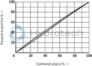
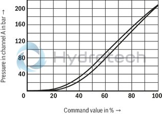
(measured with HLP46, ϑOil = 40 ±5 °C)
Pressure in port A dependent on the command value (flow = 0.8 l/min)
DRE(M)E
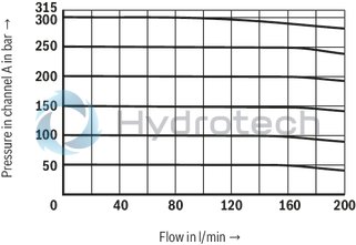
Pressure in channel A dependent on the flow qv
(characteristic curves with constant Δp)
Size 10
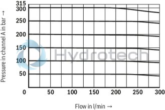
Pressure in channel A dependent on the flow qv
(characteristic curves with constant Δp)
NG25
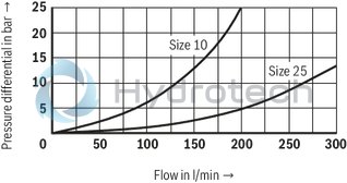
Pressure differential from A to B via the check valve
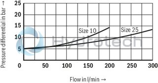
Pressure differential from B to A
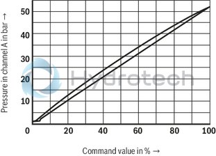
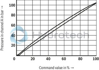
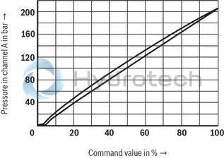
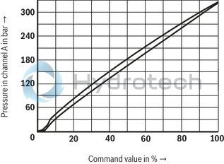
Pressure in channel A dependent on the command value
Pressure rating 50 bar
Pressure rating 100 bar
Pressure rating 200 bar
Pressure rating 315 bar
Pressure rating 200 bar (with VT-SSPA1)
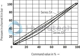
Comparison series 5X-6X / pressure rating 100 bar (with amplifier VT-VSPA1-1-1X with 800 mA coil)
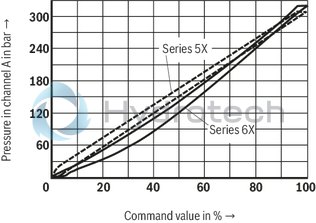
Comparison series 5X-6X / pressure rating 315 bar (with amplifier VT-VSPA1-1-1X with 800 mA coil)
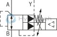
Type DREE-6X/...YM...
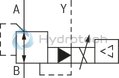
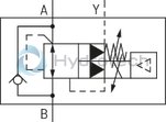
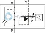
Type DREME-6X/...YM...
Type DREME-6X/...Y...
Type DREE-6X/...Y...
|
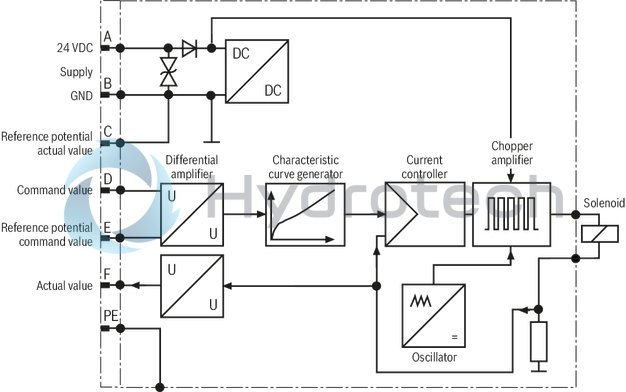
Pin assignment |
Contact |
Assignment interface "A1" |
Assignment interface "F1" |
|
Power supply |
A |
24VDC(u(t)=21...35V);Imax≤1,5A |
|
|
B |
0V |
||
|
Reference potential actual value |
C |
Reference contact F; 0 V |
Reference contact F; 0 V |
|
Differential amplifier input (command value) |
D |
0 ... 10 V; Re = 100 kΩ |
4 ... 20 mA; Re = 100 kΩ |
|
E |
Reference potential command value |
||
|
Measuring output (actual value) |
F |
0 to 1.6 V actual value (1 mV ≙ 1 mA); |
|
|
PE |
connected to solenoid and valve housing |
||
Connection cable
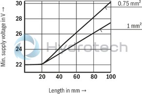
| 1) | Connection cable:- Recommendation 6-wire, 0.75 or 1mm2 plus protective earthing conductor and screening- Connect screening to PE on supply side only- Maximum admissible length 100 m The minimum supply voltage at the power supply unit depends on the length of the supply line (see diagram) |
Integrated electronics (OBE)
Function
The electronics are supplied with voltage via ports A and B. The command value is applied to the differential amplifier ports D and E.Via the characteristic curve generator, the command value solenoid current characteristic curve is adjusted to the valve so that non-linearities in the hydraulic system are compensated and thus, a linear command value pressure characteristic curve is created.The current controller controls the solenoid current independently of the solenoid coil resistance.The power stage of the electronics for controlling the proportional solenoid is a chopper amplifier with a clock frequency of approx. 180 Hz to 400 Hz. The output signal is pulse-width modulated (PWM). For checking the solenoid current, a voltage can be measured at the connector between pin F(+) and pin C(–) which is proportional to the solenoid current. 1 mV corresponds to 1 mA solenoid current.
Block diagram / pin assignment
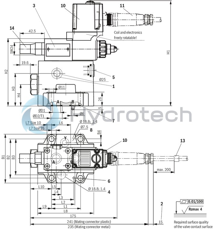
|
Size |
10 | 25 | ||
|
B1 |
mm |
85 | 102 | |
|
B2 |
mm |
66.7 | 79.4 | |
|
B3 |
58.8 mm | 73 mm | ||
|
B4 |
7.9 mm | 6.4 mm | ||
|
ØD1 |
mm |
15 | 25 | |
|
ØD2 |
H11 |
mm |
21.8 | 34.8 |
|
H1 |
mm |
192 | 206 | |
|
H2 |
mm |
123 | 137 | |
|
H3 |
mm |
58 | 64 | |
|
H4 |
mm |
36 | 44 | |
|
L1 |
mm |
42.9 | 60.3 | |
|
L2 |
mm |
35.8 | 49.2 | |
|
L3 |
mm |
31.8 | 44.5 | |
|
L4 |
mm |
21.5 | 20.6 | |
|
L5 |
mm |
7.2 | 11.1 | |
|
L6 |
21.5 mm | 39.7 mm | ||
|
L7 |
5 mm | 12.2 mm | ||
|
L8 |
116 mm | |||
|
L9 |
44.5 mm | 27.3 mm | ||
|
L10 |
59.5 mm | 42 mm | ||
|
T1 |
mm |
2 | 2.9 | |
|
1 |
Upon delivery, this port (G1/4) is closed. After removal of the blanking plug, an external and separate depressurized pilot oil return to the tank is, however, also possible here. |
|
2 |
Space required to remove the mating connector |
|
3 |
Name plate |
|
4 |
Blind counterbore |
|
5 |
Check valve, optional |
|
6 |
Locating pin |
|
7 |
Identical seal rings for ports A and B Identical seal rings for port Y and blind counterbore (pos. 4) |
|
8 |
Pilot oil return always external, separate and depressurized to the tank or optional at pos. 1 |
|
9 |
mating connector according to DIN EN 175301-803 |
|
10 |
Integrated electronics (OBE) |
|
11 |
Mating connector according to DIN EN 175201-804 |
|
12 |
Machined valve contact surface; Porting pattern according to ISO 5781-06-07-0-00 (NG10) and ISO 5781 -08-10-0-00 (NG25) |
|
13 |
Cable fastening |
|
14 |
Maximum pressure limitation with version DREM and DREME |
Recommended valve mounting screws (separate order):
4 hexagon socket head cap screws ISO 4762 - M10 x 45 - 10.9-flZn-240h-L
(Friction coefficient μtotal = 0.09 to 0.14)
Tightening torque MA = 59 Nm ± 10%
or
4 hexagon socket head cap screws ISO 4762 - M10 x 45 - 10.9
(Friction coefficient μtotal = 0.12 to 0.17)
Tightening torque MA = 75 Nm ± 10%
Notice:
The dimensions are nominal dimensions which are subject to tolerances.
Mating connectors for valves with round connector, 6-pole + PE
7P Z31
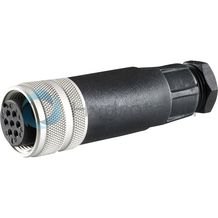
Mating connectors for valves with round connector, 6-pole + PE
7P Z31
For valves with round connector according to EN 175201-804, 6-pole + PE as well as 6-pole, compatible with VG 95328Data sheet
Spare parts & repair