


BOSCH REXROTH
R901271163
$1,826.50 USD
- BOSCH REXROTH
- Material:R901271163
- Model:M-3SED10CK1X/350CG24N9XNK4/V
Quantity in stock: 0
The Bosch Rexroth M-3SED10CK1X/350CG24N9XNK4/V (R901271163) is a high-performance directional seat valve designed for controlling the start, stop, and direction of flow in hydraulic systems. This direct-operated valve features solenoid actuation and includes a manual override function that allows for valve switching without solenoid energization. It is constructed with a durable housing, robust solenoids, precise valve seats, and a responsive control spool. The M-3SED10CK1X/350CG24N9XNK4/V valve operates on the basic principle where its initial position—either normally open (UK) or normally closed (CK)—is determined by the spring arrangement. The pressure-compensated design ensures consistent operation by balancing the actuating forces of the solenoid and spring. This valve can handle maximum operating pressures up to 350 bar and is capable of directing flow in both directions. Equipped with a throttle insert option, this model can manage excessive flows during switching processes that may otherwise surpass the performance limit of the valve. The Plus plate feature enables additional configurations by connecting port P to B and A to T in its initial position while transitioning to connect P directly to A during switching. Furthermore, this directional seat valve offers safety and reliability through its wet-pin DC solenoids that ensure safe switching even after extended periods under pressure. The solenoid coil can be rotated by 90 degrees for flexible installation, and electrical connections are made via individual connection options. For hazardous environments, it meets Explosion Protection Directive EU standards IIG and IID as well as technical rules EAC/TR CU standards IIG and IID. The type of protection for the valve solenoids is Exec II C T Gc according to EN 60079-0 and Extc II IC T Dc according to EN 60079-7. This Bosch Rexroth directional seat valve is an essential component for advanced hydraulic applications requiring precise flow control with reliable performance under varying operating conditions.
3/2 directional seat valve
General information
Directional valves of the type SED are direct operated directional seat valves with solenoid actuation. They control start, stop and direction of flow.
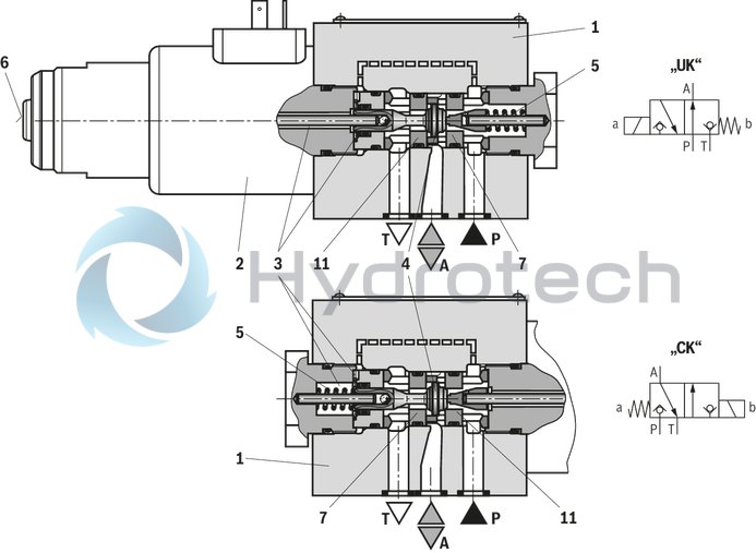
Directional valves basically comprise the housing (1), the solenoid (2), the valve seats (7) and (11) and the control spool (4).
The manual override (6) allows for the switching of the valve without solenoid energization.
Basic principle
The initial position of the valve (normally open "UK" or normally closed "CK") is determined by the arrangement of the spring (5). The chamber (3) behind the control spool (4) is connected to port P and sealed against port T. Thus, the valve is pressure-compensated in relation to the actuating forces (solenoid and spring).
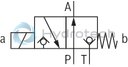
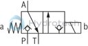
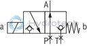
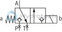
By means of the control spool (4), the ports P, A and T can be loaded with the maximum operating pressure (350 bar) and the flow can be directed into both directions (see symbols).
In the initial position, the control spool (4) is pressed onto the seat (11) by the spring (5), in spool position, it is pressed onto the seat (7) by the solenoid (2). The flow is blocked.
Seat valves can be used according to the symbols and the related operating pressures and flows (see "Performance limits").
Type M-3SED 10 UK...
Type M-3SED 10 CK...
Throttle insert "...B"
The use of a throttle insert is required when, due to prevailing operating conditions, flows occur during the switching processes, which exceed the performance limit of the valve.
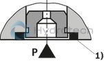
| 1) | Seal ring |
4/2 directional seat valve
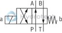
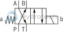
With a sandwich plate, the Plus-1 plate, under the 3/2 directional seat valve, the function of a 4/2 directional seat valve is achieved.
Function of the Plus-1 plate:
Initial position:
The main valve is not operated. The spring (5) holds the control spool (4) on the seat (11). Port P is blocked and A is connected to T. Apart from that, one control line is connected from A to the large area of the control spool (8), which is thus unloaded to the tank. The pressure applied via P now pushes the ball (9) onto the seat (10). Now, P is connected to B, and A to T.
Transition position:
Upon actuation of the main valve, the control spool (4) is shifted against the spring (5) and pressed onto the seat (7). During this, port T is blocked, while P, A, and B are briefly connected to each other.
Switching position:
P is connected to A. As the pump pressure acts via A on the large area of the control spool (8), the ball (9) is pressed onto the seat (12). Thus, B is connected to T, and P to A. The ball (9) in the Plus-1 plate has a “positive spool overlap”.
Notice:
If the annulus area of differential cylinders is not connected to port A, a pressure peak is created in port B during the switching process. This pressure peak may exceed the maximum admissible operating pressure over the permissible limit.
|
The use of the Plus-1 plate and the seat arrangement offer the following options: |
||
|
Symbol |
D 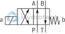
|
Y 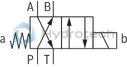
|
Type M-4SED 10 Y…
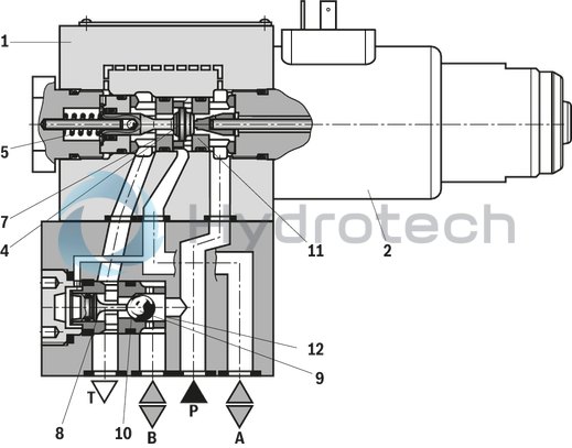
Schematic illustration: Initial position
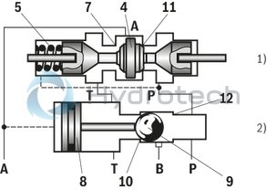
| 1) | 3/2 directional seat valve |
| 2) | Plus-1 plate |
Throttle insert, check valve insert
|
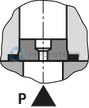
Throttle insert |
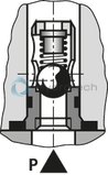
Check valve insert |
|
The use of a throttle insert is required if, due to prevailing operating conditions, flows which exceed the performance limit of the valve can occur during the switching processes. |
The check valve insert allows a free flow from P to A and closes A to P. |
|
|
|
01 |
02 |
03 |
04 |
05 |
06 |
07 |
08 |
09 |
10 |
11 |
12 |
13 |
14 |
|||
|
M |
– |
SED |
10 |
1X |
/ |
350 |
C |
G24 |
XN |
K4 |
/ |
|
01 |
Mineral oil |
M |
||
|
02 |
3 main ports |
3 |
||
|
4 main ports |
4 |
|||
|
03 |
Seat valve |
SED |
||
|
04 |
Size 10 |
10 |
||
|
Symbols |
||||
|
05 |
Main ports |
3 |
4 |
|
|
✔ |
– |
UK |
|
|
✔ |
– |
CK |
|
|
– |
✔ |
D |
|
|
– |
✔ |
Y |
|
|
06 |
Component series 10 ... 19 (10 ... 19: unchanged installation and connection dimensions) |
1X |
||
|
07 |
Operating pressure up to 350 bar |
350 |
||
|
08 |
Wet-pin solenoid with detachable coil |
C |
||
|
Voltage |
||||
|
09 |
Direct voltage 24 V |
G24 |
||
|
10 |
With concealed manual override |
N9 |
||
|
Without manual override |
no code |
|||
|
Explosion protection |
||||
|
11 |
"Not igniting", for details, please refer to the "information on explosion protection" |
XN |
||
|
Electrical connection |
||||
|
12 |
Individual connection |
|||
|
Solenoid without mating connector, see "Electrical connection" |
K4 |
|||
|
Throttle insert |
||||
|
13 |
Without check valve insert, without throttle insert |
no code |
||
|
Throttle Ø 1.2 mm |
B12 |
|||
|
Throttle Ø 1.5 mm |
B15 |
|||
|
Throttle Ø 1.8 mm |
B18 |
|||
|
Throttle Ø 2.0 mm |
B20 |
|||
|
Throttle Ø 2.2 mm |
B22 |
|||
|
Seal material (observe compatibility of seals with hydraulic fluid used, see "Technical data") |
||||
|
14 |
NBR seals |
no code |
||
|
FKM seals |
V |
|||
|
Notice: |
||||
For applications outside these parameters, please consult us!
general
|
Size |
10 | ||
|
Installation position |
any | ||
|
Ambient temperature range 1) |
°C |
-20 … +50 | |
|
Storage temperature range |
°C |
+5 … +40 | |
|
Maximum storage time |
yrs |
1 | |
|
Weight |
3/2 directional seat valve |
kg |
3.3 |
|
4/2 directional seat valve |
kg |
4.7 | |
|
Surface protection |
Galvanized | ||
| 1) | Maximum 40 °C when using the cable sets DS2513. |
hydraulic
|
Size |
10 | ||
|
Maximum operating pressure |
Port P |
bar |
350 |
|
Port A |
bar |
350 | |
|
Port B |
bar |
350 | |
|
Port T |
See performance limits | ||
|
Maximum flow |
l/min |
40 | |
|
Hydraulic fluid |
see table "Hydraulic fluid" | ||
|
Hydraulic fluid temperature range 1) |
NBR seals |
°C |
-20 … +80 |
|
FKM seals |
°C |
-15 … +80 | |
|
Viscosity range |
mm²/s |
2.8 … 500 | |
|
Maximum admissible degree of contamination of the hydraulic fluid, cleanliness class according to ISO 4406 (c) 2) |
Class 20/18/15 | ||
| 1) | Observe the "Special application conditions for safe application" |
| 2) | The cleanliness classes specified for the components must be adhered to in hydraulic systems. Effective filtration prevents faults and simultaneously increases the life cycle of the components. For the selection of the filters, see www.boschrexroth.com/filter. |
|
Hydraulic fluid |
Classification |
Suitable sealing materials |
Standards |
Data sheet |
|
|
Mineral oils |
HL, HLP, HLPD |
NBR, FKM |
DIN 51524 |
90220 |
|
|
Bio-degradable |
Insoluble in water |
HETG |
NBR, FKM |
ISO 15380 |
90221 |
|
HEES |
FKM |
||||
|
Soluble in water |
HEPG |
FKM |
ISO 15380 |
||
|
Important information on hydraulic fluids: For more information and data on the use of other hydraulicfluids, please refer to the data sheets above or contact us. There may be limitations regarding the technical valve data (temperature, pressure range, life cycle, maintenance intervals, etc.). Ignition temperature > 190 °C |
|||||
electrical
|
Voltage type |
Direct voltage | ||
|
Available voltages |
V |
24 | |
|
Voltage tolerance (nominal voltage) |
% |
± 10 | |
|
Admissible residual ripple |
% |
< 5 | |
|
Duty cycle/operating mode according to VDE 0580 |
S1 (continuous operation) | ||
|
Rated current |
mA |
950 | |
|
Switching time according to ISO 6403 1) |
ON |
ms |
40 … 80 |
|
OFF |
ms |
10 … 25 | |
|
Maximum switching frequency |
Hz |
1 | |
|
Maximum switch-off voltage peaks Solenoid 2) |
V |
500 | |
|
Nominal power with ambient temperature 20 °C |
W |
23 | |
|
Maximum power with 1.1 x nominal voltage and an ambient temperature of 20 °C |
W |
28.8 | |
|
Protection class according to DIN EN 60529 3) |
IP65 | ||
| 1) | The switching times were determined at a hydraulic fluid temperature of 40 °C and a viscosity of 46 mm2/s. Deviating hydraulic fluid temperatures can result in different switching times. Switching times change dependent on operating time and application conditions. |
| 2) | Suitable damping by user required |
| 3) | If a suitable mating connector and a correctly mounted electric connection are used. |
Information on explosion protection – Directive 2014/34/EU
|
Area of application |
II 3G | II 3D | II 3G | II 3D | ||
|
Type of protection valve |
c (EN 13463-5) | |||||
|
Type of protection valve solenoid according to EN 60079-7 / EN 60079-31 |
Ex ec IIC T3 Gc | Ex tc IIIC T140°C Dc | Ex ec IIC T3 Gc | Ex tc IIIC T140°C Dc | ||
|
Maximum surface temperature 1) |
°C |
140 | ||||
|
Temperature class |
T3 | |||||
|
Type examination certificate solenoid |
BVS 12 ATEX E 062 X | |||||
|
Requirements on the mating connector |
Temperature rating 2) |
°C |
≥ 100 | |||
|
Area of application according to directive 2014/34/EU |
II 3G | II 3D | II 3G | II 3D | ||
|
Protection class in plugged condition 3) |
IP65 | |||||
| 1) | Surface temperature > 50 °C, provide contact protection. |
| 2) | Transfer temperature at the connector of the valve solenoid 85 °C at ambient temperature 40 °C. |
| 3) | If a suitable mating connector and a correctly mounted electric connection are used. |
Information on explosion protection – Technical rules EAC TR CU 012/2011
|
Area of application |
II 3G | II 3D | II 3G | II 3D | |
|
Type of protection marking of valve |
2Ex nA II T3 Gc X | Ex tc IIIC T140°C Dc X | 2Ex nA II T3 Gc X | Ex tc IIIC T140°C Dc X | |
|
Maximum surface temperature 1) |
°C |
140 | |||
|
Temperature class |
T3 | ||||
|
Certificate of conformity |
No TC RU C-DE.ГБ08.В.02161 | ||||
| 1) | Surface temperature > 50 °C, provide contact protection. |
Special application conditions for safe application
Connection lines must be passed in a pull-relieved way. The valve is to be installed in a way that no impact stress > 4 J can become effective. In order to avoid dangers caused by static charge, the base and/or subplate on which the valve is to be fitted must be electrically conductive and included in the equipotential bonding. The valve must not be installed close to charge generating processes. Dust layers with a thickness of > 50 mm are inadmissible. Maximum hydraulic fluid temperature:In case of bank assembly, as long as only one solenoid is energized at a time and in case of individual assembly: +80 °C
In case of bank assembly, if more than one solenoids are energized simultaneously: +65 °C The maximum temperature of the surface of the valve jacket is 110 °C. This has to be considered when selecting the connection cable and/or contact of the connection cable with the surface of the jacket is to be prevented.
Performance limits (measured with HLP46, ϑoil = 40 ±5 °C)
|
Symbol |
Comment |
Operating pressure in bar |
Flow in l/min |
|||||
|
P |
A |
B |
T |
|||||
|
2-way circuit |
UK |
|
With 2/2-way circuits, port P or T must be closed. |
350 |
350 |
‒ |
350 |
40 |
|
CK |
|
350 |
350 |
‒ |
350 |
40 |
||
|
3-way circuit |
UK |
|
350 |
350 |
‒ |
350 |
40 |
|
|
CK |
|
350 |
350 |
‒ |
350 |
40 |
||
|
4-way circuit (flow only possible in the direction of arrow) |
D |
|
3/2 directional valve (symbol "UK") in connection with Plus-1 plate: pP ≥ pA ≥ pB ≥ pT |
350 |
350 |
350 |
pP/pA/pB-40 |
40 |
|
Y |
|
3/2 directional valve (symbol "CK") in connection with Plus-1 plate: pP ≥ pA ≥ pB ≥ pT |
350 |
350 |
350 |
pP/pA/pB-40 |
40 |
|
Notice:
The performance limits were determined when the solenoids were at operating temperature, at 10 % undervoltage and without tank preloading.
(measured with HLP46, ϑOil = 40 ±5 °C)
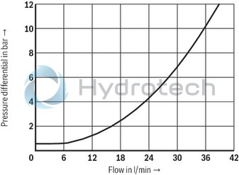
Δp-qV characteristic curves
3/2 directional seat valve
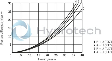
Δp-qV characteristic curves
4/2 directional seat valve
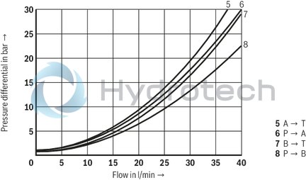
Δp-qV characteristic curves
Check valve insert
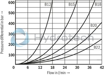
Δp-qV characteristic curves
Throttle insert
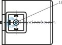
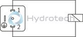
The type-examination tested valve solenoid of the valve is equipped with an electrical connection according to the following table. The electrical connection of the solenoid is polarity-independent.
Electrical connections and coil connection combinations
|
Ordering code connector |
Top view |
Circuit diagram |
Pin |
Connections, assignment |
|
|
3-pole connector (2+PE) according to DIN EN 175301-803 |
K4 |
|
|
1 |
Solenoid coil, polarity-independent |
|
2 |
|||||

|
Earthing |
||||
| 1) | M3, max. tightening torque MA max = 1 Nm |
Over-current fuse and switch-off voltage peaks
|
Voltage data in the valve type code |
Nominal voltage valve solenoid |
Rated current valve solenoid |
Recommended pre-fuse characteristics medium time-lag according to DIN EN 60127-1 |
|
G24 |
24 V DC |
0.95 A DC |
1 A |
Notice:
A fuse which corresponds to the rated current according to DIN 41571 and EN / IEC 60127 has to be connected upstream of every valve solenoid (max. 3 x Irated).
The shut-off threshold of the fuse has to match the prospective short-circuit current of the supply source.
The prospective short-circuit current of the supply source may amount to a maximum of 1500 A.
This fuse may only be installed outside the potentially explosive atmosphere or must be of an explosion-proof design.
When inductivities are switched off, voltage peaks result which may cause faults in the connected control electronics.
The voltage peak must be damped by a suitable external circuitry. We recommend a circuitry with a suppressor diode with a limitation voltage of approx. 50 V.
3/2 directional seat valve – version “UK"
Dimensions in mm
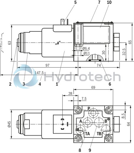
|
|
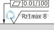
Required surface quality of the valve contact surface |
|
1 |
Solenoid coil |
|
2 |
Concealed manual override “N9” |
|
3 |
Mounting nut with double edge SW32 |
|
4 |
Space required to remove the solenoid coil |
|
5 |
Plug-in connector according to EN 175301-803, design A (Cable sets, separate order, see "Accessories") |
|
6 |
Identical seal rings for ports A, B, T; seal ring for port P |
|
7 |
Name plate |
|
8 |
Porting pattern according to ISO 4401-05-04-0-05 |
|
9 |
The ports B and TB are present as blind counterbores |
|
10 |
Name plate sticker |
3/2 directional seat valve – version "CK"
Dimensions in mm
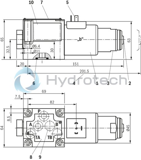
|
|
|
Required surface quality of the valve contact surface |
|
1 |
Solenoid coil |
|
2 |
Concealed manual override “N9” |
|
3 |
Mounting nut with double edge SW32 |
|
4 |
Space required to remove the solenoid coil |
|
5 |
Plug-in connector according to EN 175301-803, design A (Cable sets, separate order, see "Accessories") |
|
6 |
Identical seal rings for ports A, B, T; seal ring for port P |
|
7 |
Name plate |
|
8 |
Porting pattern according to ISO 4401-05-04-0-05 |
|
9 |
The ports B and TB are present as blind counterbores |
|
10 |
Name plate sticker |
4/2 directional seat valve – version “D”
Dimensions in mm
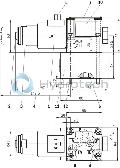
|
|
|
Required surface quality of the valve contact surface |
|
1 |
Solenoid coil |
|
2 |
Concealed manual override “N9” |
|
3 |
Mounting nut with double edge SW32 |
|
4 |
Space required to remove the solenoid coil |
|
5 |
Plug-in connector according to EN 175301-803, design A (Cable sets, separate order, see "Accessories") |
|
6 |
Identical seal rings for ports A, B, T; seal ring for port P |
|
7 |
Name plate |
|
8 |
Porting pattern according to ISO 4401-05-04-0-05 |
|
9 |
Port TB is designed as blind counterbore |
|
10 |
Name plate sticker |
|
11 |
Plus-1 plate |
|
12 |
Valve mounting screws |
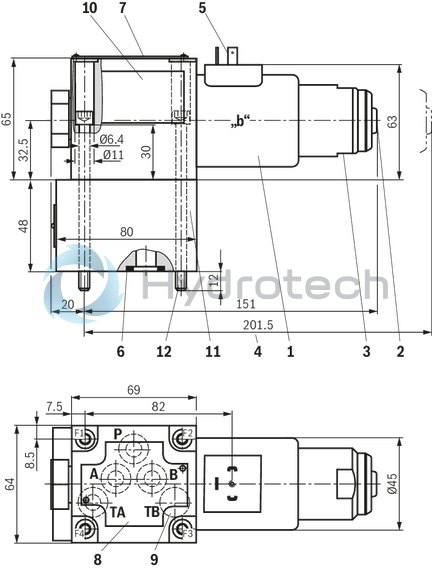
4/2 directional seat valve, version “Y”
Dimensions in mm
|
|
|
Required surface quality of the valve contact surface |
|
1 |
Solenoid coil |
|
2 |
Concealed manual override “N9” |
|
3 |
Mounting nut with double edge SW32 |
|
4 |
Space required to remove the solenoid coil |
|
5 |
Plug-in connector according to EN 175301-803, design A (Cable sets, separate order, see "Accessories") |
|
6 |
Identical seal rings for ports A, B, T; seal ring for port P |
|
7 |
Name plate |
|
8 |
Porting pattern according to ISO 4401-05-04-0-05 |
|
9 |
Port TB is designed as blind counterbore |
|
10 |
Name plate sticker |
|
11 |
Plus-1 plate |
|
12 |
Valve mounting screws |
Valve mounting screws (separate order)
|
Version |
Quantity |
Hexagon socket head cap screws |
Material number |
|
"CK", "UK" |
4 |
ISO 4762 - M6 x 40 - 10.9 (Friction coefficient μtotal = 0.09 … 0.14) |
R913051533 |
|
"D", "Y" |
4 |
ISO 4762 - M6 x 90 - 10.9 (Friction coefficient μtotal = 0.09 … 0.14) |
R913048089 |
|
Notice: For reasons of stability, exclusively these valve mounting screws are to be used. |
|||
Subplates (separate order) with porting pattern according to ISO 4401-05-04-0-05, see data sheet 45100.
Notices:
Subplates are no components in the sense of directive 2014/34/EU and can be used after the manufacturer of the overall system has conducted an assessment of the risk of ignition. The "G...J3" versions are free from aluminum and/or magnesium and galvanized. Deviating from ISO 4401, port T is in this data sheet called TA, port T1 is called TB. The dimensions are nominal dimensions which are subject to tolerances.Installation conditions
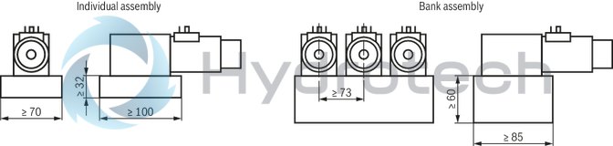
(Dimensions in mm)
|
Individual assembly |
Bank assembly |
|
|
Subplate dimensions |
Minimum dimensions: |
Minimum cross-section: |
|
Thermal conductivity of the subplate (EN-GJS-500-7) |
≥ 38 W/mK |
|
|
Minimum distance between the longitudinal valve axes |
≥ 73 |
|
Notice:
With respect to the hydraulic fluid temperature, please observe the “Special conditions for safe use” in chapter "Technical data".
Seat valves can be used according to the spool symbols as well as the assigned operating pressures and flows (see "Performance limits").
In order to ensure safe functioning, it is absolutely necessary to observe the following:
Seat valves have a negative spool overlap, i.e. during the switching process, there is leakage oil. This process takes, however, place within such a short time that it is irrelevant in nearly all applications. The specified maximum flow must not be exceeded (use a throttle insert for flow limitation, if necessary).4 main ports:
The following lower operating values have to be observed:pmin = 8 bar, qV > 3 l/min. The ports P, A, B and T are clearly specified according to their tasks. They must not be exchanged or closed. Port T must always be connected. Observe the pressure level and pressure distribution. The flow is only permitted in the direction of arrow.
Subplates
Subplates
Mating connectors for valves with connector “K4”, without circuitry, standard, with assembled connection line (ATEX)
DS2513...ATEX
Mating connectors for valves with connector “K4”, without circuitry, standard, with assembled connection line (ATEX)
DS2513...ATEX
For valves with connector “K4” according to EN 175301-803 and ISO 4400, 2-pole + PE, “large cubic connector” Mating connectors for valves with one or two solenoids (individual connection)Data sheet
Spare parts & repair