
BOSCH REXROTH
R901263599
$2,712.53 USD
- BOSCH REXROTH
- Material:R901263599
- Model:VT5041-3X/V30D
Quantity in stock: 0
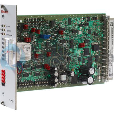
The Bosch Rexroth VT 5041-3X/V30D (R901263599) is an advanced control electronics card designed to manage systems of type SYDFE, featuring a version without power limitation and equipped with a swivel angle display. This model is specifically tailored for external control of SYDFE systems, allowing for analog communication and integration via a pin connector plug in form D. The card operates on a supply voltage of VDC and is presented in the convenient Eurocard format. The VT 5041-3X/V30D card boasts dual command value inputs for both pressure and swivel angle, with the option of power limitation. It utilizes pressure transducers to measure actual pressure values and position transducers at the pump to gauge swivel angle values. These measurements are processed through amplifiers, ensuring accurate comparison with command values. A minimum value generator ensures that only the relevant controller is activated according to the operating point needed. Furthermore, this card includes an inductive position transducer for valve spool positioning, enhanced by an oscillatordemodulator switch. The resulting control deviation is managed by a dedicated controller which outputs signals to a self-timing power output stage controlling the valve's proportional solenoid. In case of faults, indicated by a low-active voltage signal and flashing Err. LED, users can configure the system to de-energize the output stage and move the valve spool to its mechanical end position. Faults could be due to internal voltage supply errors, excessive system pressure, cable breaks or control errors among others. Additional features include adjustable pressure controller circuitry suitable for two hydraulic fluid volumes, differential amplifier inputs, pressure-dependent leakage compensation (with an option to disable), reverse polarity protection for voltage supply, switchable actual pressure value input (current or voltage), LED displays indicating operational status, and an optional display instrument for actual swivel angle value. Optional power limitation can be set internally or externally as well. In summary, the Bosch Rexroth VT 5041-3X/V30D offers comprehensive control capabilities for SYDFE systems with robust fault detection mechanisms while providing flexibility through its optional features tailored to specific application needs.
For the control of systems of type SYDFE1.
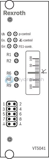
Version without power limitation with swivel angle display - Modified function / customer-specific
Unpacked Weight: 0.225201 kg
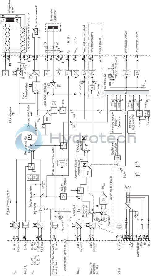
The analog control electronics VT5041-3X/... is designed as insertion card in euro format. It is provided with a command value input each for pressure and swivel angle [1] as a standard (optional power limitation). The actual pressure value is measured with a pressure transducer. The position transducer at the pump measures the actual swivel angle value. The measured actual values are processed in amplifier [2] and [3] and compared with the provided command values. The minimum value generator [4] controls that only controller [6] or [10] which is allocated to the requested operating point is automatically activated. The output signal of the minimum value generator [4] becomes the command value for the valve control loop. The optionally available power limitation is automatically activated by the provision of a suitable command value. The power command value can be provided internally or externally. If necessary, it limits the swivel angle command value by means of a minimum value generator [5]. The resulting swivel angle command value can be measured at socket 7.
The actual valve value (position of the valve spool) is measured with an inductive position transducer. An oscillator/demodulator switch [7] enhances the signal. The control deviation is generated and processed in the controller for the valve spool position [8]. The output signal of the valve controller [8] forms the command value for the self-timing power output stage [9] which controls the proportional solenoid of the valve.
The control electronics is equipped with a fault message output where a voltage of 0 V is applied in an error case (= low-active). At the same time, the "Err." LED flashes. Depending on the jumper J1 configuration, the valve output stage can be de-energized in case of an error message.
Causes for fault messages:
Error in the internal voltage supply The actual pressure value is greater than the admissible system pressure (socket 2: pact > 11.5 V) No enable signal at port 26c Cable break or range of the swivel angle return exceeded Cable break or range of the valve spool return exceeded Cable break "pressure transducer" (for adjustments 4...20 mA, 0.5...5 V and 1...10 V) Control error (control difference x controller amplification) is greater than 4 V (40 %) for more than 1 secondIn an error case, the electronics can be configured so that the output stage is de-energized and the valve spool is pressed to its mechanical end position. This causes the pump to swivel back. The error can only be acknowledged by resetting the enable signal.
[ ] = assignment see block diagram
| Communication: analog |
| External control electronics for SYDFE1 - system |
| Component series 3X |
| For the control of the axial piston variable displacement pump A10VSO... with SYDFE1 control via valve type VT-DFP...2X |
| Data Sheet | Download Data Sheet |
| Manual | Download Manual |
| Manual | Download Manual |
| Manual | Download Manual |
| Electrical connection description | 32-pin connector plug, form D |
| Productgroup ID | 9,10,11,12,13,14 |
| Supply voltage | 24 VDC |
| Design | Printed circuit board |
| Weight | 0.225201 |
|
01 |
02 |
03 |
04 |
|||
|
VT 5041 |
– |
3X |
/ |
– |
0 |
|
01 |
External control electronics for the SYDFE1 control of the A10VSO axial piston variable displacement pump |
VT 5041 |
|
02 |
Component series 30 ... 39 (30 ... 39: unchanged technical data and pin assignment) |
3X |
|
Additional functions |
||
|
03 |
Without power limitation / without display instrument |
1 |
|
Without power limitation / with display instrument |
2 |
|
|
With power limitation / with display instrument |
3 |
|
|
04 |
For IW9 swivel angle sensor (standard) |
0 |
|
Operating voltage |
UB |
24 V DC +40 –10%; (21,6 … 33,6 V) | ||||
|
Upper limit value |
UB(t)max |
V |
35 | |||
|
Lower limit value |
UB(t)min |
V |
21 | |||
|
Current consumption |
Inom |
A |
0.6 | |||
|
Imax |
A |
1.25 | ||||
|
Analog command value inputs |
Pressure |
pCOMMAND |
Ue |
0 … 10 V; Re > 50 kΩ | ||
|
Swivel angle |
SWCOMMAND |
Ue |
Standard ±10 V ; regenerative: 0 … 10 V; Re > 50 kΩ | |||
|
Power |
(p · SW)max |
Ue |
0 … 10 V; Re > 50 kΩ | |||
|
SWACT master |
Ue |
±10 V, Re > 50 kΩ | ||||
|
Analog actual value inputs |
Pressure |
pACT |
Ue |
0 ... 5 V, 0 ... 10 V; Re > 50 kΩ | ||
|
Ie |
0.5 ... 5 V, 1 ... 10 V; Re > 50 kΩ; 0 ... 20 mA, 4 ... 20 mA; RB = 100 Ω | |||||
|
Enable input |
SPS |
Ue |
> 12 V | |||
|
Analog outputs |
Output stage |
Solenoid current |
Imax |
2.5 A; R20 = 2 Ω | ||
|
Oscillator |
Frequency |
f |
kHz |
5.4 | ||
|
Amplitude for IW9 1) |
Actual swivel angle value |
uSS |
V |
1 | ||
|
Amplitude for DM2 2) |
Actual valve value |
uSS |
V |
3.6 | ||
|
Signal voltage outputs |
Actual pressure value |
U |
0 … 10 V | |||
|
Actual swivel angle value |
U |
–10 V … +10 V ≙ –100 % ... +100 % | ||||
|
Auxiliary voltages for external use |
U |
±(15 V +2 % –6 %); Imax = 10 mA | ||||
|
Measuring sockets, function and number |
Pressure command value |
1 |
pCOMMAND |
U |
0 … 10 V ≙ 0 … +100 %; Ri = 2 kΩ | |
|
Actual pressure value |
2 |
pACT |
U |
0 … 10 V ≙ 0 … +100 %; Ri = 2 kΩ | ||
|
Swivel angle command value |
3 |
SWCOMMAND |
U |
±10 V ≙ ±100 %; Ri = 2 kΩ | ||
|
Actual swivel angle value |
4 |
SWACT |
U |
±10 V ≙ ±100 %; Ri = 2 kΩ | ||
|
Valve command value |
5 |
x_vsoll |
U |
±10 V ≙ ±100 %; Ri = 2 kΩ | ||
|
Actual valve value |
6 |
x_vist |
U |
±10 V ≙ ±100 %; Ri = 2 kΩ | ||
|
Active swivel angle command value |
7 |
U |
±10 V ≙ ±100 %; Ri = 2 kΩ | |||
|
Power limit |
8 |
Pmax |
U |
0 … 10 V ≙ 0 … +100 %; Ri = 2 kΩ | ||
|
Message outputs |
Swivel angle control enabled |
U |
UB – 3V (Imax = 20 mA) | |||
|
Power limitation active |
U |
UB – 3V (Imax = 20 mA) | ||||
|
Fault messages |
Low-active |
U |
UB – 3 V (Imax = 20 mA) | |||
|
High-active |
U |
UB – 3 V (Imax = 20 mA) | ||||
|
Type of transducer |
Swivel angle |
IW9 |
inductive position transducer |
Throttle circuit; ±4 mm; 3-conductor connection | ||
|
Valve |
DM2 |
inductive position transducer |
Trafo circuit; ±0.6 mm; 4-conductor port | |||
|
Type of connection |
Compatibility |
32-pole Male multipoint connector; DIN 41612; design D | ||||
|
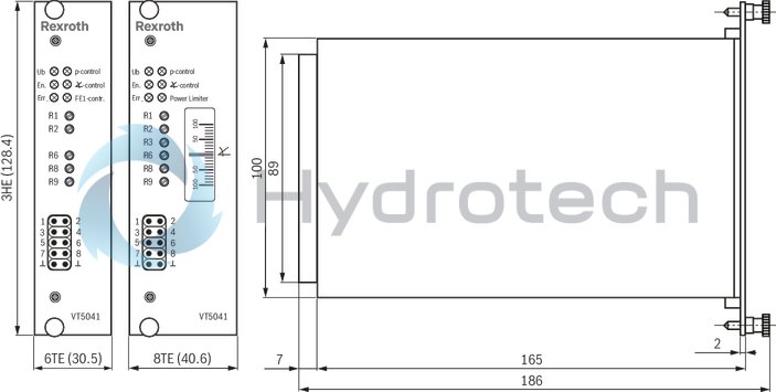
Card dimensions |
Euro-card 100 x 160 mm; DIN 41494 | |||||
|
Front plate dimensions |
Height |
3 HE (128,4 mm) | ||||
|
Width |
Conductor path side |
1 TE | ||||
|
Component side |
VT 5041-3X/1-0 |
5 TE | ||||
|
VT 5041-3X/2-0 and VT 5041-3X/3-0 |
7 TE | |||||
|
Operating temperature range |
ϑ |
°C |
0 … +50 | |||
|
Storage temperature range |
ϑ |
°C |
-20 … +70 | |||
|
Mass |
Electronic card |
without display |
m |
kg |
0.19 | |
|
with display |
m |
kg |
0.21 | |||
| 1) | Port 12a/14a |
| 2) | Port 8a |
For applications outside these parameters, please consult us!
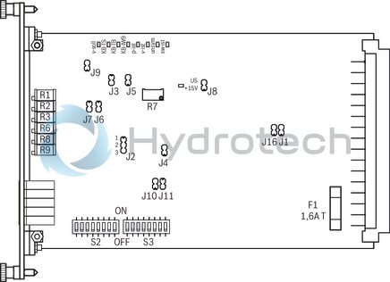
Pin assignment
|
Leakage compensation |
Jumper |
|
|
J6 |
J7 |
|
|
Off |
OFF |
OFF |
|
4 % |
OFF |
ON |
|
6 % |
ON |
OFF |
|
10 % |
ON |
ON |
|
Valve command value monitoring |
Jumper |
|
J9 |
|
|
On |
ON |
|
Off * |
OFF |
|
Regenerative operation |
Jumper |
|
|
J3 |
J5 |
|
|
On |
ON |
OFF |
|
Off |
OFF |
ON |
|
Function pin 18a ** |
Jumper |
|
J4 |
|
|
Pressure control |
OFF |
|
Master/slave |
ON |
|
** Only for versions without power limitation (VT 5041-3X/1-0 and VT 5041-3X/2-0) |
|
|
Selection for analog input at pin 18c |
Jumper |
|
J2 |
|
|
Bridge |
|
|
Actual master swivel angle value |
1-2 |
|
external power limitation |
2-3 |
|
Pressure controller p amplification |
Switch S3 |
Jumper |
|
|
.7 |
.8 |
J11 |
|
|
8,0 |
OFF |
OFF |
OFF |
|
4,8 |
OFF |
ON |
OFF |
|
4,0 |
OFF |
OFF |
ON |
|
3,0 |
OFF |
ON |
ON |
|
2,4 |
ON |
OFF |
ON |
|
2,0 |
ON |
ON |
ON |
|
Volume adjustment of pressure controller |
|||
|
Input switch TD = OFF |
Switch S3 |
||
|
.1 |
.2 |
.3 |
|
|
≤ 5,0 l |
OFF |
OFF |
OFF |
|
7,5 l |
OFF |
ON |
OFF |
|
10,0 l |
ON |
ON |
OFF |
|
15,0 l |
ON |
OFF |
ON |
|
20,0 l |
OFF |
ON |
ON |
|
25,0 l |
ON |
ON |
ON |
|
Input switch TD = ON |
Switch S3 |
||
|
.4 |
.5 |
.6 |
|
|
12,5 l |
OFF |
OFF |
OFF |
|
30,0 l |
OFF |
ON |
OFF |
|
45 l |
ON |
ON |
OFF |
|
60 l |
ON |
OFF |
ON |
|
75 l |
OFF |
ON |
ON |
|
90 l |
ON |
ON |
ON |
|
Actual pressure value amplification |
Jumper |
|
J10 |
|
|
1-fold |
OFF |
|
2-fold |
ON |
|
Explanations: |
|
|
ON |
Bridge closed |
|
OFF |
Bridge open |
|
Factory setting |
|
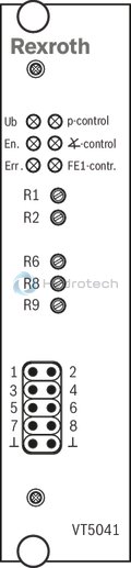
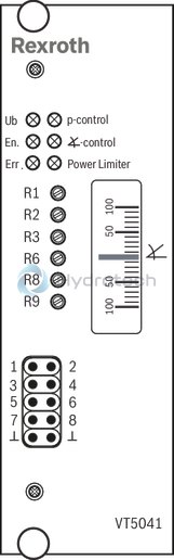
For the meaning of the measuring sockets, display and adjustment elements (potentiometer) on the front plate, see front plate.
|
Valve switch-off in case of error |
Jumper |
|
J1 |
|
|
Active |
OFF * |
|
Inactive |
ON |
|
* compatible with VT 5041-2X |
|
| 1) | LED displays on the front plate (meaning see front plate) |
| 2) | For further information with regard to the connection, see operating instructions 30011-B |
Function of the jumpers and switches on the electronic card see Electronic card.
For the meaning of the measuring sockets, display and adjustment elements (potentiometer) at the front plate, see front plate.
VT 5041-3X/1-0
VT 5041-3X/2-0
VT 5041-3X/3-0
|
Diagnosis LEDs |
|
For a description, see block diagram and the operating instructions 30011-B |
|
Signal adjustment of actual pressure value |
Switch S2 |
||||||||
|
.1 |
.2 |
.3 |
.4 |
.5 |
.6 |
.7 |
.8 |
||
|
V |
0...10 V |
OFF |
OFF |
OFF |
OFF |
OFF |
OFF |
ON |
ON |
|
E |
1...10 V |
OFF |
OFF |
OFF |
OFF |
ON |
OFF |
OFF |
ON |
|
D |
0...5 V |
OFF |
OFF |
ON |
ON |
OFF |
OFF |
ON |
ON |
|
F |
0,5...5 V |
OFF |
OFF |
ON |
ON |
ON |
OFF |
OFF |
ON |
|
B |
0...20 mA |
ON |
ON |
OFF |
OFF |
OFF |
OFF |
ON |
ON |
|
C |
4...20 mA |
ON |
ON |
OFF |
OFF |
ON |
ON |
OFF |
OFF |
Dimensions in mm
Card holder
VT 3002-2X
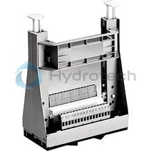
Card holder
VT 3002-2X
Component series 2XData sheet
Configurator / CAD
Spare parts & repair