


BOSCH REXROTH
R901238530
$563.47 USD
- BOSCH REXROTH
- Material:R901238530
- Model:VT-SSPA1-5-1X/V0/0-24/K24
Quantity in stock: 0
The Bosch Rexroth VT-SSPA1-5-1X/V0/0-24/K24 (R901238530) is an advanced plugin amplifier designed for precise control in hydraulic systems. This device is adept at installation on a valve connection base compliant with EN standards, offering versatility through 90-degree rotation increments for optimal positioning on the solenoid. The command value presetting feature allows for a range between 0 and UB, ensuring that solenoid current remains proportional to the command value within a specified voltage range and nearly constant at higher values according to the Imax setting for reliable switching applications. The integrated ramp generator is engineered to manage the rate of change in the control output, with separate adjustments available for both ascending and descending ramp times. This functionality is crucial in mitigating the impact of switch-on and switch-off impulses, contributing to smoother transitions in operation. Notably, conductor connection influences this feature, highlighting its dependency on specific valve and solenoid types without affecting ramp time by the command value attenuator. Bosch Rexroth has meticulously designed the characteristic curve of this amplifier to ensure linear progression up to a certain command value threshold. Adjustments can be made using potentiometers Z for zero-point correction and G for maximum value tuning. The power output stage employs a freely clocking mechanism where clock frequency is adjusted by potentiometer f, tailored according to current levels, operating voltage, and solenoid impedance—balancing valve hysteresis against system noise levels. Furthermore, this model features a differential input only and offers an analog interface with connector design suitable for KBPS valves. It supports a regulated adjustable maximum current for high-command values and includes components like zero potentiometer for pilot current adjustment, command value attenuator for maximum current control, and dither frequency potentiometer—all within a component series X package that operates effectively at 24V.
The plug-in amplifier is suitable for installation on a valve connection base according to EN 175301-803. By turning the plug insert and the electronics in the housing, the plug-in amplifier can be mounted on the solenoid in 90° increments.
Command value presetting
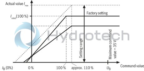
The command value range is between 0 and UB. In the command value range 0... 10 V the solenoid current is proportional to the command value. Starting with a command value of 12 V up to UB the solenoid current is almost constant according to the Imax setting (switching application).
Ramp generator
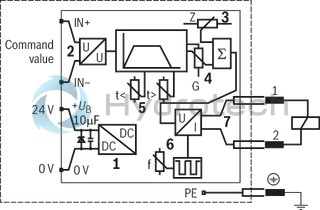
The ramp generator (5) limits the incline of the control output. The up and down ramp times can be adjusted separately. In switching applications, the ramps can be used to dampen the switch-on and switch-off impulse (When switching off only with 3-conductor connection, i.e. switching signal and supply are connected separately). This behavior also depends on the valve and solenoid type. The downstream command value attenuator (4) has no influence on the ramp time.
Characteristic curve
Up to a command value of approx. 110 % the transfer characteristic curve rises linearly. The zero point can be corrected using potentiometer “Z“, the maximum value can be corrected using potentiometer “G“.
Power output stage
Output stage (7) is freely clocking. The clock frequency depends on the current level, the operating voltage and the impedance of the controlled solenoid. The clock frequency can be re-adjusted using potentiometer “f“. The current output stage generates a regulated current signal according to the control output provided by the summing device (3). If the clock frequency is too high, the valve hysteresis is increased. If the clock frequency is too low, the noise level of the hydraulic system is increased.
()= Assignment to the block diagram
|
01 |
Valve amplifiers for proportional valves without electrical position feedback, Analog, Connector design |
VT-SSPA1 |
|
02 |
For valves: KBPS 8 |
5 |
|
03 |
Component series 10 ... 19 (10 ... 19: unchanged installation and connection dimensions) |
1X |
|
04 |
Version: standard |
V0 |
|
05 |
Voltage input |
0 |
|
06 |
24 V operating voltage |
24 |
|
07 |
With cable gland |
No code |
|
With M12 connector |
K24 |
|
01 |
02 |
03 |
04 |
05 |
06 |
07 |
||||||
|
VT-SSPA1 |
‒ |
5 |
‒ |
1X |
/ |
V0 |
‒ |
0 |
‒ |
24 |
/ |
General
|
Component series |
1X | ||
|
Type of electronics |
Analog | ||
|
Design |
Plug-in connector |
Voltage supply
|
Operating voltage |
nominal |
U |
V |
24 |
|
Lower limit value |
UB(t)min |
V |
18 | |
|
Upper limit value |
UB(t)max |
V |
35 | |
|
Cable inductance 1) |
max. |
Lmax |
µH |
100 |
|
Power consumption |
max. |
Smax |
VA |
40 |
|
Current consumption |
max. |
Imax |
A |
1.7 |
|
Fuse |
2 A time-lag | |||
| 1) | Usually corresponds to a line length < 100 m. |
Analog inputs
|
Command value |
Voltage (differential input) |
U |
V |
0 ... 10 | |
|
for the switching function of the proportional amplifier |
12 ... UB | ||||
|
Voltage (differential input) |
Input resistance |
R |
kΩ |
≥ 20 | |
Solenoid outputs
|
Coil inductivity |
min. |
Lmin |
mH |
15 |
|
Pilot current |
Factory setting |
Iv |
mA |
0 |
|
Solenoid current |
Factory setting |
I |
A |
1.2 |
|
Coil resistance at 20°C |
R(20) |
Ω |
4.77 | |
|
Clock frequency |
at Imax |
f |
Hz |
200 |
Adjustment options
|
Setting range |
Pilot current |
IB |
mA |
0 ... 300 |
|
Solenoid current |
Imax |
A |
0 ... 1.8 | |
|
Ramp time up/down |
t |
s |
0.06 … 5 | |
Supplementary information
|
Standard connection |
of solenoid |
EN 175301-803 | ||
|
Anschlussart |
Cable gland and screw terminals | |||
|
alternatively |
M12 connector, 4-pole | |||
|
Cable diameter |
L |
mm |
4.5 ... 11 | |
|
Mounting type |
L |
M3 x 40 mm | ||
|
Type of protection according to EN 60529 1) |
Extra für FN |
IP65 | ||
|
Ambient temperature range |
ϑ |
°C |
-25 … 70 | |
|
Storage temperature range |
ϑ |
°C |
-25 … 85 | |
|
Weight |
m |
kg |
0.125 | |
| 1) | With mounted cable/mounted mating connector |
For applications outside these parameters, please consult us!
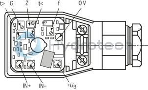
|
G |
Command value attenuator / maximum current |
|
Z |
Zero point potentiometer / pilot current |
|
t < |
Ramp time "Ramp up" |
|
t > |
Ramp time "Ramp down" |
|
f |
Clock frequency |
|
(1) |
Internal voltage adjustment |
|
(2) |
Voltage input |
|
(3) |
Zero point potentiometer “Z” / pilot current I (IN = 0 %) |
|
(4) |
Command value attenuator “G” / maximum current I (IN = 100 %) |
|
(5) |
Ramp time potentiometer “t<” and “t>” |
|
(6) |
Frequency range correction “f” |
|
(7) |
Power output stage |
|
Terminal / pin |
Signal designation |
|
+UB / 1
|
Operating voltage |
|
0 V / 3 |
0 V |
|
IN+ / 2 |
Command value |
|
IN- / 4 |
Reference potential |
Terminal connection
Danger of malfunctions
in case of EMC/ESD interferences affecting the connection cable
Do not install command value
connection lines in the gray area (arrow)!
The connection for protective earthing conductor is accessible after the
electronic circuit board has been removed.
Connection cross-section:
4 x 0.75 mm2 shielded or
5 x 0.5 mm2 shielded (connect shield in the control cabinet)
Terminal connection
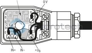
M12 connector, top view

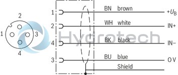
The connection for protective earthing conductor is not provided
Connection cross-section:
4 x 0.75 mm2 shielded
(connect shield in control cabinet)
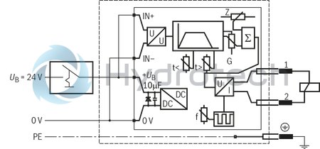
2-conductor technology
Switching application with constant current control Ramp function upon switch-onThe “IN+” input is bridged with supply voltage (+UB) in the connector, the IN- input is bridged with supply voltage (0 V) in the connector.
The maximum current must generally be adjusted according to the solenoid information using potentiometer "G". The ramp time "ramp up" (t <) can be set within the range of tmin to 5 s.
2-conductor technology
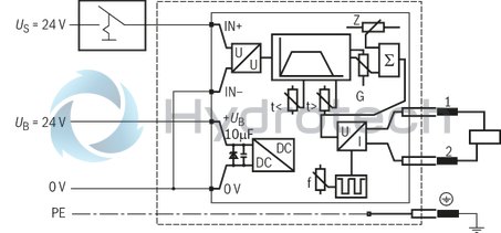
3-conductor technology
Switching application with constant current control
Switching with low control power
Ramp function can be adjusted separately when switching the control voltage on and off
The “IN+” input is connected to the control voltage
(Us = 24 V), the “IN–” input is bridged with supply voltage (0 V) in the connector.
The maximum current must generally be adjusted according to the solenoid information using potentiometer "G". When switched off ("IN+" = 0 V or "IN+" = open), a pilot current can be set at "Z". It serves to reduce the switch-on delay, particularly with ramp. If required, this value can be adjusted between approx. 0 mA and approx. 15 % of the rated current. The ramp times “ramp up” (t <) and “ramp down” – (t >) can be set within the range of tmin to 5 s.
3-conductor technology
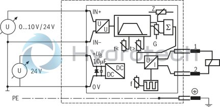
4-conductor technology
The “IN+” input is connected to the control signal (Us = 0...10 V/24 V), the “IN–” input to the reference potential of the control voltage.
Pilot current and maximum current are set using potentiometers "Z" and "G" prior to commissioning. The current can now be proportionally adjusted according to the control voltage between the set pilot current and the set maximum current. The pilot current can be set in the range from approx. 0 to approx. 15 % of the rated current, the maximum current can be set in the range from 0 to Imax .
4-conductor technology
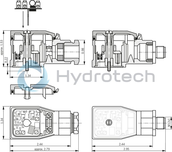
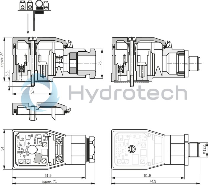
The connector insert can be turned in 90° steps observing the protective measures for ESD protection.
The plug-in amplifier may only be wired when de-energized.
Do not lay lines close to power cables.
The distance to aerial lines, radios, and radar systems has to be at least 1 m.
To set the potentiometers and to check the current values, use the measuring adapter and measure the currents in a potential-free manner.
The specified maximum solenoid currents must not be exceeded.
Do not use solenoids with integrated free-wheeling diodes.
The supply voltage is to be protected by means of a fuse – see Technical data.
Notice:
The solenoids are controlled with a clocked voltage. The solenoid voltage impulse level corresponds to the applied operating voltage (+UB).
Solenoids with integrated EMC protection circuit may only be used if the response voltage of the protection circuit - for both, positive and negative voltage - is greater than the actual operating voltage.
The manufacturer's specifications of the valves are to be observed.
Notice:
With a strongly fluctuating operating voltage, it may in the individual case be necessary to use an external smoothing capacitor with a capacity of at approx. 470 µF to 2200 µF.
The line length should not exceed 50 m. For longer lines, a capacitor with C ≥ 100 µF has to be connected between UB and 0 V. The line between capacitor and plug-in amplifier must not exceed 50 m.
Recommendation: VT 11110 capacitor module (see data sheet 30750); sufficient for up to 5 plug-in amplifiers