

BOSCH REXROTH
R901210122
$119.38 USD
- BOSCH REXROTH
- Material:R901210122
- Model:ABZMM 63- 600BAR/MPA-R/B330G
Quantity in stock: 0
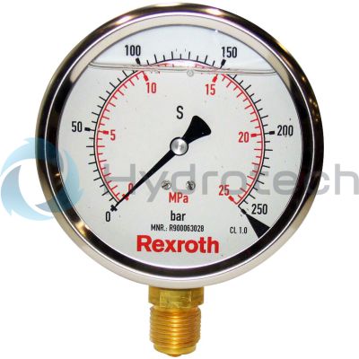
The Bosch Rexroth ABZMM 63-600BAR/MPA-R/B330G (R901210122) is a high-quality pressure gauge designed for accurately measuring and displaying pressure within hydraulic systems. The gauge is calibrated to display pressures in both bar and MPa, ensuring versatility and precision for a range of applications. This model is crafted in accordance with the EN standard, which guarantees its reliability and performance. With a robust stainless steel housing, the ABZMM 63-600BAR/MPA-R/B330G is built to withstand challenging environments while maintaining its integrity over time. It features a bicolored scale that enhances readability and user-friendliness. The maximum pressure it can measure reflects its capability to perform in industrial settings where monitoring hydraulic pressure is critical. The type of connection is designed with a mounting bracket for secure installation, and the connection point is located on the rear side of the gauge for convenience. This particular model comes with various hydraulic fluid compatibility options including HLP, HFC, HFDR, HFDU, HETG, HEES, and HEPG, making it suitable for diverse hydraulic systems. Additionally, users can benefit from different mounting options such as screws or brackets according to their specific requirements. The design ensures that the measuring connection at the back or bottom does not interfere with system operations while providing easy access for maintenance or calibration checks. In summary, the Bosch Rexroth ABZMM 63-600BAR/MPA-R/B330G (R901210122) offers reliability, durability, and precision for professionals seeking an accurate pressure gauge for their hydraulic systems. Its compatibility with multiple fluids and adherence to industry standards make it an essential instrument in maintaining system efficiency and safety.
For measuring and displaying pressure in hydraulic systems
Unpacked Weight: 0.2939 kg
| Pressure displayed in bar/MPa |
| Pressure gauges are pressure measuring instruments for measuring and displaying pressure in hydraulic systems |
| Design according to standard EN 837-2 |
| Housing made of stainless steel |
| Data Sheet | Download Data Sheet |
| Type of connection | with mounting bracket |
| Max. pressure | 600 |
| Productgroup ID | 9,10,11,12,13,14 |
| Connection diagram | Male thread G1/4 B |
| Connection point | Rear side |
| Weight | 0.2939 |
| Hydraulic fluid | HLP,HFC,HFDR,HFDU,HETG,HEES,HEPG |
Ordering code
|
01 |
02 |
03 |
04 |
05 |
06 |
07 |
08 |
09 |
|||
|
ABZM |
M |
‒ |
‒ |
/ |
|
Power unit accessories |
||
|
01 |
Measuring devices |
ABZM |
|
Pressure gauge |
||
|
02 |
Pressure gauge with bourdon tube |
M |
|
Size |
||
|
03 |
DN40 |
40 |
|
DN63 |
63 |
|
|
DN100 |
100 |
|
|
Display range |
||
|
04 |
See selection table |
… |
|
Version |
||
|
05 |
Double scale in pressure range bar and MPa |
BAR/MPA |
|
Double scale in pressure range bar and psi |
BAR/PSI |
|
|
Position of the measuring port |
||
|
06 |
On the back side |
R |
|
At the bottom |
U |
|
|
Mounting type |
||
|
07 |
With fitting |
V |
|
With mounting bracket |
B |
|
|
Option |
||
|
08 |
Without option |
‒ |
|
Red marking at the dial, e.g. at 330 bar |
330 |
|
|
Pressure gauge filling |
||
|
09 |
With glycerin (standard) |
G |
|
With silicone filling as low-temperature version |
T |
|
|
Order example: Pressure gauge with housing Ø63 mm and double scale with a display range from 0 to 25 bar, measuring port at bottom, without mounting element: ABZMM-63-25 BAR/MPA-U/V-G |
|
Display range |
||
|
bar |
MPa |
psi |
|
10 |
1 |
145 |
|
16 |
1,6 |
230 |
|
25 |
2,5 |
362 |
|
40 |
4 |
580 |
|
60 |
6 |
870 |
|
100 |
10 |
1450 |
|
160 |
16 |
2320 |
|
250 |
25 |
3625 |
|
400 |
40 |
5800 |
|
600 |
60 |
8700 |
|
1000 |
100 |
14500 |
DN40Connection on the back side 
|
DN63Port on bottom 
|
DN100Port on bottom 
|
||
DN63Connection on the back side 
|
DN100Connection on the back side 
|
Resistance
|
Hydraulic fluids |
Resistant |
|||
|
Mineral oils |
Mineral oil |
HLP |
according to DIN 51524 |
|
|
Flame-resistant hydraulic fluids |
Water solutions |
HFC |
according to VDMA 24317 |
|
|
Phosphoric acid esters |
HFD-R |
|||
|
Organic esters |
HFD-U |
|||
|
Fast bio-degradable hydraulic fluids |
Triglycerides (rape seed oil) |
HETG |
according to VDMA 24568 |
|
|
Synthetic esters |
HEES |
|||
|
Polyglycols |
HEPG |
|||
|
Water |
Water |
|||
|
Gases |
||||
|
Nitrogen (others gases upon request) |
||||
For applications outside these parameters, please consult us!
Symbol

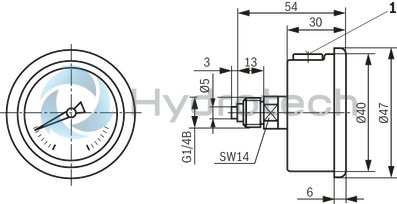
Dimensions: Pressure gauge DN40, with dual scale – connection centrally at the rear
Dimensions in mm
|
1 |
Bleed or pressure unloading opening |
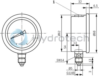
Dimensions: Pressure gauge DN63, with dual scale – connection at the bottom
Dimensions in mm
|
1 |
Bleed or pressure unloading opening |
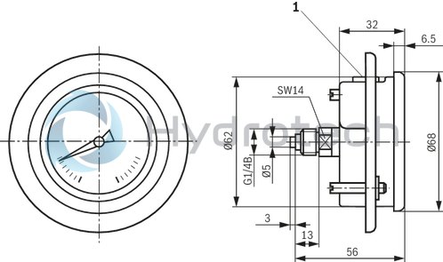
Dimensions: Pressure gauge DN63, with dual scale – connection centrally at the rear, with mounting clamp
Dimensions in mm
|
1 |
Bleed or pressure unloading opening |
Break-through Ø63+1 mm
Mounting bracket is included in the scope of delivery of the pressure gauge.
Design according to the manufacturer’s choice.
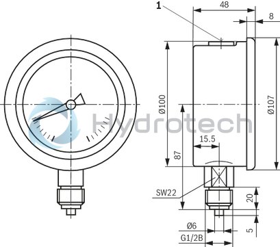
Dimensions: Pressure gauge DN100, with dual scale – connection at the bottom
Dimensions in mm
|
1 |
Bleed or pressure unloading opening |
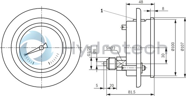
Dimensions: Pressure gauge DN100, with dual scale – connection eccentrically at the rear, with mounting clamp
Dimensions in mm
|
1 |
Bleed or pressure unloading opening |
Break-through Ø101+1 mm
Mounting bracket is included in the scope of delivery of the pressure gauge.
Design according to the manufacturer’s choice.
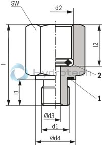
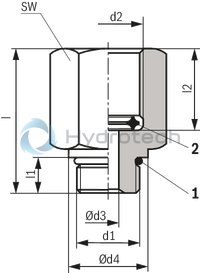
Dimensions: Adapter for direct installation of the pressure gauge
Version "A"
Reducing piece for mounting cavity to ISO 1179
Version "B"
Reducing piece for mounting cavity to ISO 11926-1
|
Version |
PN |
d1 |
d2 |
Ød3 |
Ød4 |
l |
l1 |
l2 |
SW |
Denomination |
Part number |
|
mm |
mm |
mm |
mm |
mm |
|||||||
| A | 630 | G1/4A | G1/4 | 4 | 19 | 34 | 12 | 14.5 | 22 | REDUZIERSTUECK G1/4-G1/4 /FKM | R901156422 |
| 400 | G1/4A | G1/2 | 4 | 19 | 35 | 12 | 16 | 27 | REDUZIERSTUECK G1/4-G1/2 /FKM | R901156423 | |
| B | 630 | 7/16-20UNF | G1/4 | 4 | 16 | 31 | 9 | 14.5 | 22 | REDUZIERSTUECK 7/16-20UNF-G1/4 /FKM | R901156316 |
| 400 | 7/16-20UNF | G1/2 | 4 | 16 | 32 | 9 | 16 | 27 | REDUZIERSTUECK 7/16-20UNF-G1/2 /FKM | R901156317 |
Order example
Reducing piece made of steel, galvanised and yellow-chromated as surface protection G1/4A, female thread = G1/2 with seal ring item 1, material FKM and seal ring item 2, material Cu
REDUZIERSTUECK G1/4-G1/2 /FKM, Material no. R901156423
Spare part: seal ring item 1
|
Version |
Material |
Denomination |
Part number |
| A | FKM | PROFILDICHTUNG M14X1,5+G1/4 FKM | R900012502 |
| B | FKM | O-Ring 8,92x1,83-FKM80+-5SH | R900024577 |
Spare part: Seal ring item 2
|
For thread d2 |
Material |
Ød5 |
Ød6 |
s |
Denomination DICHTRING.... |
Part number |
|
mm |
mm |
mm |
||||
| G1/4 | Cu | 5.9 | 9.3 | 3.2 | 5,9/9,3X3,2-CU NR:9090800 | R900004667 |
| G1/2 | Cu | 8 | 14.8 | 4.2 | 8,0/14,8X4,2-CU NR:9090819 | R900218724 |

Seal ring for metal sealing. After sealing has been achieved, the pressure gauge can still be turned by 360°, so that any desired position can be set.
Installation information
When assembling the measuring line at the pressure gauge, the pressure gage connection piece (SW14; SW22) is to be held by means of a counter wrench. Bleeding and/or pressure relief openingThe pressure gauges are equipped with bleeding facilities at the top side of the housings. Before commissioning the pressure gauges, the bleeding facilities are to be manually set from the “closed” position to the “open” position in order to avoid measuring errors.Marking on the dial
On dual scales, the lettering of the outer scale division (bar) is black, that of the inner scale division red.
Note: Single or dual scales for other pressure ranges (psi, kPa, MPa) on request.
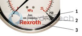
|
1 |
Part number |
|
2 |
Accuracy class according to DIN EN 837 |
|
3 |
"REXROTH" logo |
Normative cross-reference
DIN EN 837-1
Pressure gauges - part 1: Bourdon tube pressure gauges; dimensions, metrology, requirements and testing
DIN EN 837-2
Pressure gauges - part 2: Selection and installation recommendations for pressure gauges
DIN 51524
Pressure fluids; hydraulic oils
VDMA 24317
Fluid power - flame-retardant hydraulic fluids – technical minimum requirements
VDMA 24568
Fluid power; fast bio-degradable hydraulic fluids; technical minimum requirements;
Safety note according to Pressure Equipment Directive 97/23/EC
Pressure gauges are classified as pressure-holding equipment according to Article 1, Paragraph 2.1.4 of the Pressure Equipment Directive. The volume of the pressurised housings is < 0,1 l.
According to Annex 2, Diagram 4 (fluids) and Diagram 2 (nitrogen) the pressure gauges according to the present data sheet R.50205 are subject to the Pressure Equipment Directive up to PS = 1000 bar. According to Article 3, Paragraph 3 they are manufactured according to "good engineering practice" and are not CE-marked.
Use in potentially explosive atmospheres according to Directive 94/9/EC (ATEX)
The pressure gauges are provided with stainless steel housings which cannot generate igniting sparks according to DIN EN 13463-5.
The maximum surface temperature depends not on the pressure gauges, but mainly on the relevant fluid temperature and must therefore be assessed within the risk analysis of the power unit/block.
Because the pressure gauge according to the present data sheet R.50205 do not include any potential sources of ignition, they do not fall under the ATEX Directive and are not CE-marked.