


BOSCH REXROTH
R901188191
$5,131.73 USD
- BOSCH REXROTH
- Material:R901188191
- Model:E-3SE6U7X/420G96N9K4
Quantity in stock: 0
The Bosch Rexroth E-3SE6U7X/420G96N9K4 (R901188191) is a direct operated directional seat valve with solenoid actuation designed for controlling the start, stop, and direction of fluid flow within hydraulic systems. This valve, part of the component series X, is capable of handling maximum operating pressures up to 420 bar and allows for a maximum flow rate as specified by the manufacturer. The E-3SE6U7X/420G96N9K4 features a robust housing that encloses the solenoid, a hardened valve system, and utilizes a ball as its closing element to ensure leak-free closure of blocked ports. The valve operates on a basic principle where in its initial position, the ball is held against the seat by a spring and can be actuated by the solenoid. The unique design ensures that the valve system remains pressure-compensated for reliable performance under varying conditions. Its manual override function allows it to be switched without solenoid energization. Moreover, this model comes with detent capabilities which enable it to maintain its switched position independently of solenoid power. Additionally, this directional seat valve offers different seat arrangements for various switching positions—either connecting ports P and A while blocking T or vice versa—providing flexibility in application use. It also includes options for using throttle inserts or check valve inserts to accommodate specific operational requirements such as avoiding pressure intensification or ensuring free flow in one direction while preventing backflow. With an airgap DC solenoid and electrical connections designed for individual connection, along with porting patterns according to ISO standards and locating hole features, this Bosch Rexroth directional seat valve ensures safe switching even after extended periods under pressure without operation. Its size and specifications make it suitable for various hydraulic applications demanding high-pressure capabilities and precise flow control.
3/2–Wege–Sitzventil
General
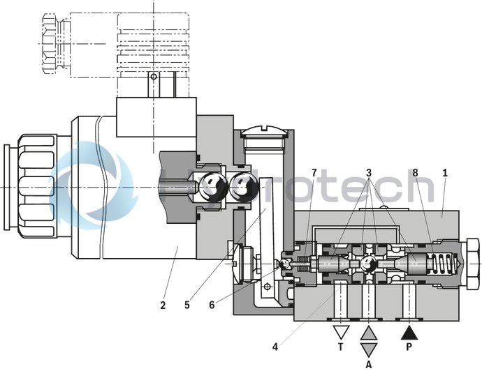
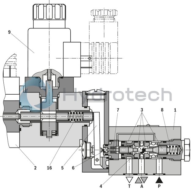
The directional valve of the E-.SE type is a directional seat valve with solenoid actuation. It controls the start, stop and direction of flow. It mainly comprises a housing (1), the solenoid (2), the hardened valve system (3) as well as the ball (4) as closing element.
Basic principle
In the initial position, the ball (4) is pressed onto the seat by the spring (8) and by the solenoid (2) in switching position. The force of the solenoid (2) acts via the angled lever (5) and the ball (6) on the actuating plunger (7), which is sealed. The chamber between the two sealing elements is connected to port P. Therefore, the valve system (3) is pressure-compensated in relation to the actuating forces (solenoid or return spring). Therefore, the valves can be used up to 630 bar.
Notice!
3/2-directional seat valves feature "negative spool overlap". Therefore, port T must always be connected. That means that during the switching process – from the starting of the opening of one valve seat to the closing of the other valve seat – ports P–A–T are connected with each other. However, this process takes place within such a short time that it is irrelevant in nearly all cases of use. The manual override allows for the switching of the valve without solenoid energization.Attention!
It is to be ensured that the maximum flow indicated is not exceeded! If applicable, a throttle insert for flow limitation is to be inserted (see functional description).
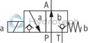
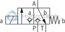
The seat arrangement offers the following options:
|
Symbol |
„U“ |
|
|
|
Initial position |
P and A connected, T blocked |
|
Switching positions |
P blocked, A and T connected |
|
Symbol |
„C“ |
|
|
|
Initial position |
P blocked, A and T connected |
|
Switching positions |
P and A connected, T blocked |
Type .-3SE 6 U …
3/2 directional seat valve – with detent
In principle, the function of this valve corresponds to the version without detent.
The detent enables the valve to stay in the switched position even if no solenoid is energized. This allows the valve to independently stay in both switching positions.
Detent function:
The solenoid (2) switches the valve into the switching position, which is latched automatically. The switching solenoid can be switched off once the switching process has been completed.
In order to leave the latched position, the solenoid (9) must be switched for a minimum of 100 ms. With the installed spring (16), the valve is returned to its basic position.
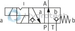
The seat arrangement offers the following options:
|
Symbol |
„U“ |
|
|
|
Initial position |
P and A connected, T blocked |
|
Switching positions |
P blocked, A and T connected |
|
Symbol |
„C“ |
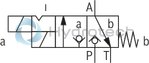
|
|
|
Initial position |
P blocked, A and T connected |
|
Switching positions |
P and A connected, T blocked |
Type .-3SE 6 U./F…
4/2 directional seat valve
With a sandwich plate, the Plus-1 plate, under the 3/2 directional seat valve, the function of a 4/2 directional seat valve is achieved.
Function of the Plus-1 plate:
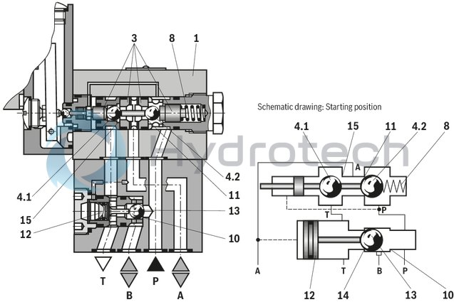
Initial position:The main valve is not operated. The spring (8) holds the ball (4.2) on the seat (11). Port P is blocked and A is connected to T. Apart from that, one control line is connected from A to the large area of the control spool (12), which is thus unloaded to the tank. The pressure applied via P now pushes the ball (13) onto the seat (14). Now, P is connected to B, and A to T.
Transition position:When the main valve is actuated, the ball (4.1) is shifted against the spring (8) and pressed onto the seat (15). During this, port T is blocked, while P, A, and B are briefly connected to each other.
Switching position:P is connected to A. As the pump pressure acts via A on the large area of the control spool (12), the ball (13) is pressed onto the seat (10). Thus, B is connected to T, and P to A. The ball (13) in the Plus-1 plate has a "positive spool overlap".
Attention!
In order to avoid pressure intensification when using differential cylinders, the annulus area of the cylinder must be connected at A.
4/2 directional seat valves with detent, analog to the 3/2 directional seat valve.
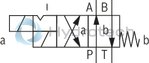
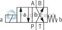
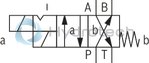
The use of the Plus-1 plate and the seat arrangement offer the following options:
|
Without detent |
With detent |
|
|
Symbol “D” |
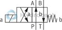
|
|
|
Symbol “Y” |
|
|
Type .-4SE 6 Y …
Throttle insert
The use of a throttle insert is required if, due to prevailing operating conditions, flows which exceed the performance limit of the valve can occur during the switching processes.
Examples:
Accumulator operation, use as pilot control valve with internal pilot fluid tapping.3/2 directional seat valve
The throttle insert is inserted into port P of the seat valve.
4/2 directional seat valve
The throttle insert is inserted into port P of the Plus-1 plate.
Check valve insert
The check valve insert allows a free flow from P to A and closes A to P in a leak-free form.
3/2 directional seat valve
The check valve insert is inserted into port P of the seat valve.
4/2 directional seat valve
The check valve insert is inserted into port P of the Plus-1 plate.
|
01 |
02 |
03 |
04 |
05 |
06 |
07 |
08 |
09 |
10 |
11 |
12 |
13 |
14 |
15 |
||
|
/ |
SE |
6 |
7X |
/ |
K4 |
* |
|
01 |
Oil-in-water emulsion, water glycol, mineral oil |
E |
|||
|
02 |
3 main ports |
3 |
|||
|
4 main ports |
4 |
||||
|
03 |
Seat valve, electrically operated |
SE |
|||
|
04 |
Size 6 |
6 |
|||
|
05 |
Main ports |
3 |
4 |
||
|
Symbols |
|
● |
– |
U |
|
|
|
● |
– |
C |
||
|
|
– |
● |
D |
||
|
|
– |
● |
Y |
||
|
● = available |
|||||
|
06 |
Component series 70 ... 79 (70 ... 79: unchanged installation and connection dimensions) |
7X |
|||
|
07 |
With spring return |
no code |
|||
|
With detent |
F |
||||
|
08 |
Operating pressure 420 bar |
420 bar |
|||
|
Operating pressure 630 bar |
630 bar |
||||
|
09 |
Direct voltage 24 V |
G24 |
|||
|
Nominal voltage 96 V at DC solenoid with operation with AC voltage mains (AC voltage mains 110 V/120 V - 50/60 Hz with an admissible voltage tolerance of +/- 10 %) |
G96 |
||||
|
Nominal voltage 110 V at DC solenoid with operation with AC voltage mains (AC voltage mains 110 V/120 V – 50/60 Hz with an admissible voltage tolerance of +/-10 %) |
G110 |
||||
|
Nominal voltage 205 V at DC solenoid with operation with AC voltage mains (AC voltage mains 230 V - 50/60 Hz with an admissible voltage tolerance of +/- 10 %) |
G205 2) |
||||
|
Further ordering codes for other voltages are provided in the technical data |
|||||
|
10 |
With concealed manual override (standard) |
N9 |
|||
|
Without manual override |
no code |
||||
|
Electrical connection |
|||||
|
11 |
without mating connector, individual connection with connector according to DIN EN 175301-803 |
K4 1) |
|||
|
12 |
Without check valve insert, without throttle insert |
no code |
|||
|
With check valve insert |
P |
||||
|
Throttle Ø 0.8 mm |
B08 |
||||
|
Throttle Ø 1.0 mm |
B10 |
||||
|
Throttle Ø 1.2 mm |
B12 |
||||
|
Throttle Ø 1.5 mm |
B15 |
||||
|
Throttle Ø 1.8 mm |
B18 |
||||
|
Throttle Ø 2.0 mm |
B20 |
||||
|
Seal material |
|||||
|
13 |
NBR seals |
no code |
|||
|
FKM seals (other seals upon request) |
V |
||||
|
Observe compatibility of seals with hydraulic fluid used. |
|||||
|
14 |
Without locating hole |
no code |
|||
|
With locating hole and locking pin ISO 8752-3x8-St |
/62 |
||||
|
15 |
Further details in the plain text |
* |
|||
| 1) Mating connectors must be ordered separately. | |
| 2) For connection to the AC voltage mains, a DC solenoid valve must be used, which is controlled via a rectifier (see ordering codes for the AC voltage mains). | |
| A mating connector with integrated rectifier can be used (separate order). |
general
|
Size |
6 | ||
|
Weight |
3/2 directional seat valve without detent |
kg |
3.8 |
|
3/2 directional seat valve with detent |
kg |
5.6 | |
|
4/2 directional seat valve without detent |
kg |
4.6 | |
|
4/2 directional seat valve with detent |
kg |
6.4 | |
|
Installation position |
any | ||
|
Ambient temperature range 1) |
°C |
-15 … +50 | |
| 1) | Mineral oil |
hydraulic
|
Size |
6 | ||
|
Maximum operating pressure |
Port P |
bar |
420 630 |
|
Port A |
bar |
420 630 |
|
|
Port B |
bar |
420 630 |
|
|
Maximum flow |
l/min |
25 | |
|
Hydraulic fluid |
see table | ||
|
Hydraulic fluid temperature range 1) |
°C |
-15 … +80 | |
|
Viscosity range |
mm²/s |
0.6 … 500 | |
|
Maximum admissible degree of contamination of the hydraulic fluid, cleanliness class according to ISO 4406 (c) 2) |
Class 20/18/15 according to ISO 4406 (c) | ||
| 1) | Mineral oil |
| 2) | The cleanliness classes specified for the components must be adhered to in hydraulic systems. Effective filtration prevents faults and simultaneously increases the life cycle of the components. For the selection of the filters, see www.boschrexroth.com/filter. |
|
Hydraulic fluid |
Classification |
Suitable sealing materials |
Standards |
|
|
Oil-in-water emulsion, water glycol, mineral oil |
HL, HLP |
FKM, NBR |
DIN 51524 |
|
|
Bio-degradable |
Insoluble in water |
HEES (synthetic esters) |
FKM |
VDMA 24568 |
|
HETG (rape seed oil) |
FKM, NBR |
|||
|
Soluble in water |
HEPG (polyglycols) |
FKM |
VDMA 24568 |
|
|
Other hydraulic fluids on request |
||||
electrical
|
Voltage type |
Direct voltage | AC voltage | ||
|
Available voltages |
V |
12 / 24 / 42 / 48 / 96 / 110 / 205 1) | 110 / 120 / 230 | |
|
Voltage tolerance (nominal voltage) |
% |
± 10 | ||
|
Power consumption |
Solenoid valve |
W |
35 | |
|
Solenoid detent |
W |
30 | ||
|
Duty cycle |
% |
100 | ||
|
Switching time according to ISO 6403 |
ON (420 bar) |
ms |
40 … 70 | |
|
ON (630 bar) |
ms |
50 … 80 | ||
|
OFF (420 bar) |
ms |
20 … 30 | ||
|
OFF (630 bar) |
ms |
15 … 40 | ||
|
Maximum switching frequency |
Hz |
3600 | ||
|
Operating pressure ≤350 bar |
Hz |
3600 | ||
|
Protection class according to DIN EN 60529 |
IP65 (with mating connector mounted and locked) | |||
|
Maximum coil temperature |
°C |
150 | ||
| 1) | Other voltages upon request |
In the electrical connection, the protective earthing conductor (PE, grounded) is to be connected in accordance with the stipulations.
For applications outside these parameters, please consult us!
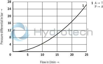
(measured with HLP46, ϑOil = 40 ±5 °C)
Δp-qV characteristic curves ‒ 3/2 directional seat valve
Δp-qV characteristic curves ‒ 4/2 directional seat valve
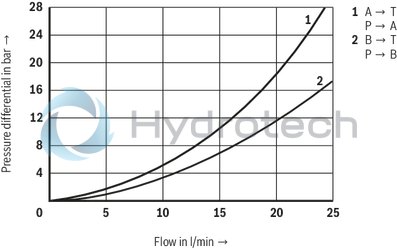
Δp-qV characteristic curves ‒ Check valve insert
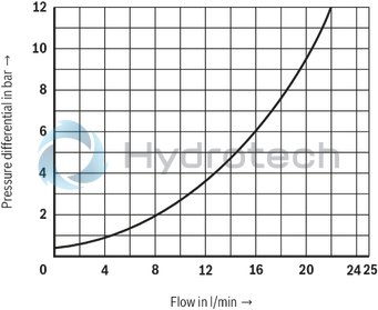
Δp-qV characteristic curves ‒ throttle insert
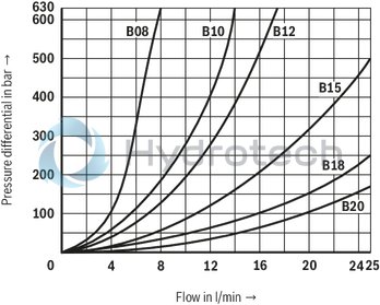
Performance limit: (measured with HLP46, ϑoil = 40 ±5 °C)
|
Symbol |
Comment |
||
|
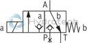
3-way circuit |
U |
|
Pressure pP ≥ pA ≥ pT |
|
C |
|
||
|
2-way circuit (as unloading function only) |
U |
|
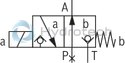
Before switching from the initial position to the switching position, pressure must be applied to port A. pA ≥ pT |
|
C |
|
Pressure pA ≥ pT |
|
|
4-way circuit (flow only possible in the direction of arrow) |
D |
|
Valve (symbol “U”) in connection with Plus-1 plate pP > pA ≥ pB > pT |
|
Y |
|
Valve (symbol “C”) in connection with Plus-1 plate pP > pA ≥ pB > pT |
|
Attention! Please observe the “General notices”!
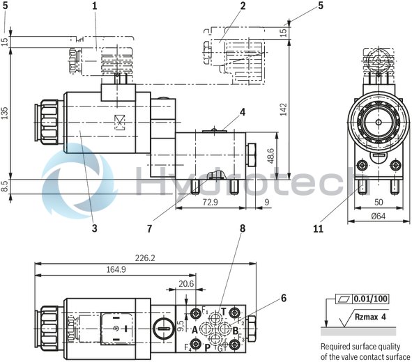
3/2 directional seat valve
Dimensions in mm
|
1 |
Mating connector without circuitry (separate order) |
|
2 |
Mating connector with circuitry (separate order) |
|
3 |
DC solenoid |
|
4 |
Name plate |
|
5 |
Space required to remove the mating connector |
|
6 |
Attention!With 3/2 directional seat valves, port B is not available in 420 bar version as blind counterbore, in 630 bar version. |
|
7 |
Identical seal rings for ports A, B, P, and T |
|
8 |
Porting pattern according to ISO 4401-03-02-0-05 (with locating hole and locking pin ISO 8752-3x8-St); deviating from the standard: version ”630” |
|
11 |
Valve mounting screws (included in the scope of delivery) 420 bar version:4 hexagon socket head cap screws ISO 4762 M5 x 50 - 10.9-flZn-240h-L (Friction coefficient μtotal = 0.09 to 0.14); Tightening torque MA = 7 Nm ± 10%, 630 bar version (not according to ISO 4401):4 hexagon socket head cap screws ISO 4762 M6 x 50 - 10.9-flZn-240h-L (Friction coefficient μtotal = 0.09 to 0.14); Tightening torque MA = 12.5 Nm ± 10% |
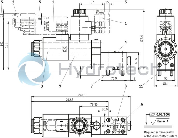
3/2 directional seat valve – with detent
Dimensions in mm
|
1 |
Mating connector without circuitry (separate order) |
|
2 |
Mating connector with circuitry (separate order) |
|
3 |
DC solenoid |
|
4 |
Name plate |
|
5 |
Space required to remove the mating connector |
|
6 |
Attention!With 3/2 directional seat valves, port B is not available in 420 bar version as blind counterbore, in 630 bar version. |
|
7 |
Identical seal rings for ports A, B, P, and T |
|
8 |
Porting pattern according to ISO 4401-03-02-0-05 (with locating hole and locking pin ISO 8752-3x8-St); deviating from the standard: version ”630” |
|
9 |
Detent with DC solenoid |
|
11 |
Valve mounting screws (included in the scope of delivery) 420 bar version:4 hexagon socket head cap screws ISO 4762 M5 x 50 - 10.9-flZn-240h-L (Friction coefficient μtotal = 0.09 to 0.14); Tightening torque MA = 7 Nm ± 10%, 630 bar version (not according to ISO 4401):4 hexagon socket head cap screws ISO 4762 M6 x 50 - 10.9-flZn-240h-L (Friction coefficient μtotal = 0.09 to 0.14); Tightening torque MA = 12.5 Nm ± 10% |
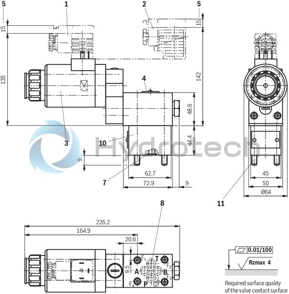
4/2 directional seat valve
Dimensions in mm
|
1 |
Mating connector without circuitry (separate order) |
|
2 |
Mating connector with circuitry (separate order) |
|
3 |
DC solenoid |
|
4 |
Name plate |
|
5 |
Space required to remove the mating connector |
|
7 |
Identical seal rings for ports A, B, P, and T |
|
8 |
Porting pattern according to ISO 4401-03-02-0-05 (with locating hole and locking pin ISO 8752-3x8-St); deviating from the standard: version ”630” |
|
10 |
Plus-1 plate |
|
11 |
Valve mounting screws (included in the scope of delivery) 420 bar version:4 hexagon socket head cap screws ISO 4762 M5 x 95 - 10.9-flZn-240h-L (Friction coefficient μtotal = 0.09 to 0.14); Tightening torque MA = 7 Nm ± 10%, 630 bar version (not according to ISO 4401):4 hexagon socket head cap screws ISO 4762 M6 x 95 - 10.9-flZn-240h-L (Friction coefficient μtotal = 0.09 to 0.14); Tightening torque MA = 12.5 Nm ± 10% |
4/2 directional seat valve – with detent
Dimensions in mm
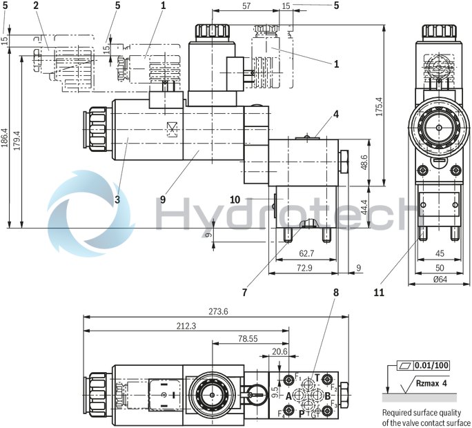
|
1 |
Mating connector without circuitry (separate order) |
|
2 |
Mating connector with circuitry (separate order) |
|
3 |
DC solenoid |
|
4 |
Name plate |
|
5 |
Space required to remove the mating connector |
|
7 |
Identical seal rings for ports A, B, P, and T |
|
8 |
Porting pattern according to ISO 4401-03-02-0-05 (with locating hole and locking pin ISO 8752-3x8-St); deviating from the standard: version ”630” |
|
9 |
Detent with DC solenoid |
|
10 |
Plus-1 plate |
|
11 |
Valve mounting screws (included in the scope of delivery) 420 bar version:4 hexagon socket head cap screws ISO 4762 M5 x 95 - 10.9-flZn-240h-L (Friction coefficient μtotal = 0.09 to 0.14); Tightening torque MA = 7 Nm ± 10%, 630 bar version (not according to ISO 4401):4 hexagon socket head cap screws ISO 4762 M6 x 95 - 10.9-flZn-240h-L (Friction coefficient μtotal = 0.09 to 0.14); Tightening torque MA = 12.5 Nm ± 10% |
In order to switch the valve safely or maintain its spool position, the pressure situation must be as follows: P ≥ A ≥ T (for design reasons). The ports P, A and T (3/2 directional seat valve) as well as P, A, B and T (4/2 directional seat valve) are clearly determined according to their tasks. They must not be arbitrarily exchanged or closed! The flow is only admissible in the direction of arrow. When using the Plus-1 plate (4/2 directional function), the following lower operating values are to be observed:
pmin = 8 bar; qV > 3 l/min.
The total flow of the valve must not be exceeded.Mating connectors for valves with connector “K4”, with indicator light
3P Z5L
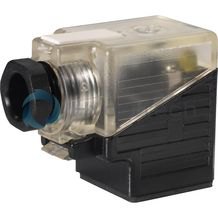
Mating connectors for valves with connector “K4”, with indicator light
3P Z5L
For valves with connector “K4” according to EN 175301-803 and ISO 4400, 2-pole + PE, “large cubic connector” Mating connectors for valves with one or two solenoids (individual connection)Data sheet
Spare parts & repair
Mating connectors for valves with connector “K4”, with indicator light and Zener diode suppression circuit
3P Z5L1
Mating connectors for valves with connector “K4”, with indicator light and Zener diode suppression circuit
3P Z5L1
For valves with connector “K4” according to EN 175301-803 and ISO 4400, 2-pole + PE, “large cubic connector” Mating connectors for valves with one or two solenoids (individual connection)Data sheet
Spare parts & repair
Mating connectors for valves with connector “K4”, with rectifier
3P RZ5
Mating connectors for valves with connector “K4”, with rectifier
3P RZ5
For valves with connector “K4” according to EN 175301-803 and ISO 4400, 2-pole + PE, “large cubic connector” Mating connectors for valves with one or two solenoids (individual connection)Data sheet
Spare parts & repair