
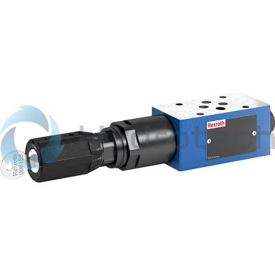
BOSCH REXROTH
R901161012
$362.00 USD
- BOSCH REXROTH
- Material:R901161012
- Model:Z3DR 6 VP2-1X/50MSV/12 GO2
Quantity in stock: 0
The Bosch Rexroth Z3DR6VP2-1X/50MSV/12 (R901161012) is a high-performance industrial hydraulic valve designed for reliable pressure reduction to a preset value. This spool valve is pilot-operated, with a pressure adjustment range that ensures precise control of secondary pressures. It features a sleeve with a hexagon and protective cap, and it belongs to component series X, indicating its compliance with the latest engineering standards. The Z3DR6VP2-1X/50MSV/12 valve has a maximum pressure capacity and is suitable for various hydraulic fluids including HL, HLP, HLPD, HVLP, HVLPD, HETG, HEES, HEPG, HFDU, and HFDR. It comes equipped with FKM seals which are known for their chemical resistance and durability. The valve is designed with multiple ports and allows mechanical actuation. This model's capabilities include flat discharge pressure curves for consistent performance, high stability across operations, and minimal hysteresis. A unique feature of this version MS is the ability to measure and monitor the set secondary pressure through a measuring port which facilitates the maintenance and adjustment processes. In case of an overpressure scenario at the actuator port P, the Z3DR6VP2-1X/50MSV/12 will open an additional line to the tank port T to safeguard against any undue pressure increase. This safety feature ensures protection for both the system and components involved. The sandwich plate design of this valve allows for easy integration into various systems with connection diagrams conforming to NFPA T3.5.1 R2 D03 Size 6 CETOP D03 standards as well as ISO 4401 size 03 patterns. With its robust build quality and versatile application potential in controlling secondary pressures in hydraulic systems, this Bosch Rexroth valve represents precision engineering tailored for demanding industrial environments.
Size 6, P2 → P1, mechanical
Industrial hydraulic valve in a high performance range. Reliable pressure reduction to setting value.
Unpacked Weight: 1.290 kg
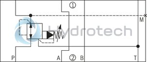
Valve type Z3DR are pilot-operated 3-way pressure reducing valves in sandwich plate design with pressure limitation of the actuator. They serve for reduction and control of secondary pressure.
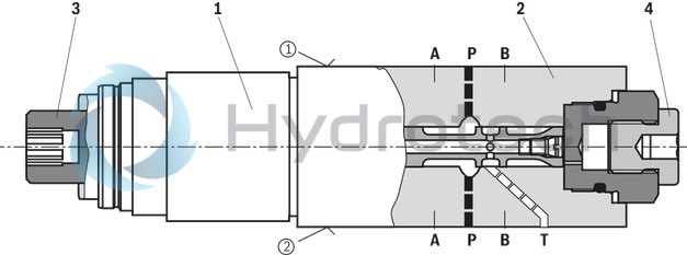
The valves basically consist of pilot control valve (1) and housing (2) including main stage. The secondary pressure is set via the adjustment type (3).
Rexroth pilot-operated pressure reducing valves feature flat discharge pressure curves, high stability and low hysteresis.
Version "MS" enables measurement and monitoring of the set secondary pressure via a pressure load cell at the measuring port (4) (refer to Dimensions).
If the secondary pressure at actuator port P① further exceeds the set value, the third line to tank port T is opened by the valve. This way, the actuator channel is protected against inadmissible pressure rise.
|
① |
component side |
|
② |
plate side |
| Spool valve |
| Pilot-operated |
| Pressure adjustment range 14…100 bar |
| Internal hexagon with protective cap |
| Maximum operating pressure 350 bar |
| Maximum flow 60 l/min |
| Size 6 |
| Component series 1X |
| Data Sheet | Download Data Sheet |
| 3D CAD | Download 3D CAD |
| Manual | Download Manual |
| Manual | Download Manual |
| Manual | Download Manual |
| Manual | Download Manual |
| Manual | Download Manual |
| Spool symbol | P2 → P1 |
| Max. pressure | 300 |
| Productgroup ID | 9,10,11,12,13,14 |
| Number of ports | 4 |
| Type of actuation | with mechanical actuation |
| Size | 6 |
| Max. flow | 60 |
| Type of connection | Sandwich plate |
| Connection diagram NFPA | NFPA T3.5.1 R2-2002 D03 |
| Size_CETOP | D03 |
| Connection diagram | ISO 4401-03-02-0-05 |
| Number of switching positions | 3 |
| Weight | 1.290 |
| Seals | FKM |
| Hydraulic fluid | HL,HLP,HLPD,HVLP,HVLPD,HETG,HEES,HEPG,HFDU,HFDR |
|
01 |
02 |
03 |
04 |
05 |
06 |
07 |
08 |
09 |
10 |
11 |
12 |
||
|
Z |
3 |
DR |
6 |
V |
P |
- |
1X |
/ |
|
01 |
Sandwich plate valve |
Z |
|
02 |
3-way version |
3 |
|
03 |
Pressure reducing valve |
DR |
|
04 |
Size 6 |
6 |
|
05 |
Pilot-operated |
V |
|
Pressure reduction |
||
|
06 |
In channel P➀ |
P |
|
Adjustment type |
||
|
07 |
Spindle with internal hexagon and protective cap ("J3" version without protective cap) |
2 |
|
Lockable rotary knob with scale 1) |
3 |
|
|
08 |
Component series 10 ... 19 (10 ... 19: unchanged installation and connection dimensions) |
1X |
|
Pressure rating |
||
|
09 |
Set pressure up to 50 bar |
50 |
|
Set pressure up to 100 bar |
100 |
|
|
Set pressure up to 200 bar |
200 |
|
|
Set pressure up to 315 bar |
315 |
|
|
Pressure measuring port G1/4 |
||
|
10 |
Without pressure measuring port |
no code |
|
With pressure measuring port (secondary pressure) |
MS |
|
|
Corrosion resistance |
||
|
11 |
None |
no code |
|
Improved corrosion protection (240 h salt spray test according to EN ISO 9227); (only version "2") |
J3 |
|
|
Seal material |
||
|
12 |
NBR seals |
no code |
|
FKM seals |
V |
|
|
Observe compatibility of seals with hydraulic fluid used. |
||
| 1) | H-Key with material no. R900008158 is included in the scope of delivery. |
Notice:
For valve types for use in explosive areas, refer to data sheet 07011.
general
|
Size |
6 | ||
|
Weight |
Version "2" |
kg |
1.3 |
|
Version "3" |
kg |
1.4 | |
|
Installation position |
any | ||
|
Ambient temperature range |
°C |
-15 … +80 | |
|
MTTFD values according to EN ISO 13849 1) |
yrs |
75 … 600 | |
| 1) | For further details, see data sheet 08012 |
hydraulic
|
Size |
6 | |||
|
Maximum operating pressure |
bar |
350 | ||
|
Maximum return flow pressure 1) |
bar |
160 | ||
|
Maximum set pressure |
Version |
50 |
bar |
50 |
|
100 |
bar |
100 | ||
|
200 |
bar |
200 | ||
|
315 |
bar |
315 | ||
|
Maximum flow |
l/min |
60 | ||
|
Hydraulic fluid |
see table | |||
|
Hydraulic fluid temperature range |
°C |
-15 … +80 | ||
|
Viscosity range 2) |
mm²/s |
10 … 500 | ||
|
Maximum admissible degree of contamination of the hydraulic fluid 3) |
Class 20/18/15 according to ISO 4406 (c) | |||
| 1) | Ideally depressurized to the tank. Counter pressure adds to the set pressure. |
| 2) | Preferably 50 … 120 mm2/s |
| 3) | The cleanliness classes specified for the components must be adhered to in hydraulic systems. Effective filtration prevents faults and simultaneously increases the life cycle of the components. For the selection of the filters, see www.boschrexroth.com/filter. |
|
Hydraulic fluid |
Classification |
Suitable sealing materials |
Standards |
Data sheet |
|
|
Mineral oils |
HL, HLP |
NBR, FKM |
DIN 51524 |
90220 |
|
|
Bio-degradable 1) |
Insoluble in water |
HETG |
NBR, FKM |
ISO 15380 |
90221 |
|
HEES |
FKM |
||||
|
Soluble in water |
HEPG |
FKM |
ISO 15380 |
||
|
Flame-resistant |
Water-free |
HFDU (glycol base) |
FKM |
ISO 12922 |
90222 |
|
HFDU (ester base) 1) |
FKM |
||||
|
Containing water 1) |
HFC (Fuchs Hydrotherm 46M, Petrofer Ultra Safe 620) |
NBR |
ISO 12922 |
90223 |
|
|
Important information on hydraulic fluids: For more information and data on the use of other hydraulic fluids, please refer to the data sheets above or contact us. There may be limitations regarding the technical valve data (temperature, pressure range, life cycle, maintenance intervals, etc.). The ignition temperature of the hydraulic fluid used must be 40 K higher than the maximum surface temperature. Flame-resistant – containing water: Maximum operating pressure 210 bar, otherwise increased cavitation erosion Life cycle as compared to operation with mineral oil HL, HLP 30 … 100 % Maximum hydraulic fluid temperature 60 °C |
|||||
| 1) | In connection with the corrosion-protected version “J3”, small amounts of dissolved zinc may get into the hydraulic system. |
For applications outside these parameters, please consult us!
(measured with HLP46, ϑOil = 40 ±5 °C)
Δp-qv characteristic curves
Pressure rating 50 bar
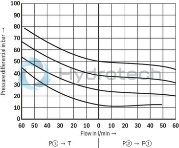
Pressure rating 100 bar
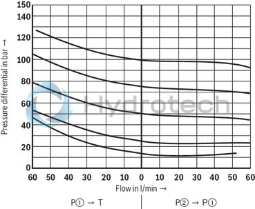
Pressure rating 200 bar

Pressure rating 315 bar
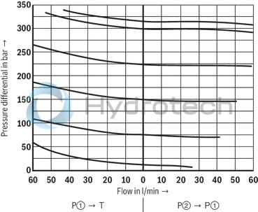
Without pressure measuring port "no code"

With pressure measuring port "MS"
|
① |
component side |
|
② |
plate side |
Dimensions in mm
|
|
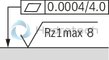
Required surface quality of the valve contact surface |
|
➀ |
component side – porting pattern according to ISO 4401-03-02-0-05 (with locating hole Ø4 x 4 mm deep) |
|
➁ |
plate side – Porting pattern according to ISO 4401-03-02-0-05 (with locating hole Ø3 x 5 mm deep for locking pin ISO 8752-3x8-St, material no. R900005694, separate order) |
|
1 |
Name plate |
|
2 |
Adjustment type "2" (spindle with internal hexagon SW8 and lock nut SW24) |
|
3 |
Adjustment type "3" |
|
4.1 |
Without measuring port (standard) |
|
4.2 |
Measuring port (version "MS"); when loosening the plug screw (SW6 internal hexagon, tightening torque MA = 20 Nm ±10 %), hold the SW24 reducing piece in place |
|
5 |
Valve mounting bores |
|
6 |
Identical seal rings for ports A, B, P, T (plate side) |
|
7 |
Space required to remove the key |
|
8 |
Protective cap (not included with version "J3") |
Valve mounting screws (separate order)
4 hexagon socket head cap screws ISO 4762 - M5 - 10.9
Notices:
Length and tightening torque of the valve mounting screws must be calculated according to the components mounted under and over the sandwich plate valve. The dimensions are nominal dimensions which are subject to tolerances.|
Denomination |
Part number |
|
Protective cap |
R900135501 |
|
Locking pin ISO 8752-3x8-St |
R900005694 |