

BOSCH REXROTH
R901134620
$15,008.11 USD
- BOSCH REXROTH
- Material:R901134620
- Model:VT-HNC100-3-3X/P-I-00/000
Quantity in stock: 0
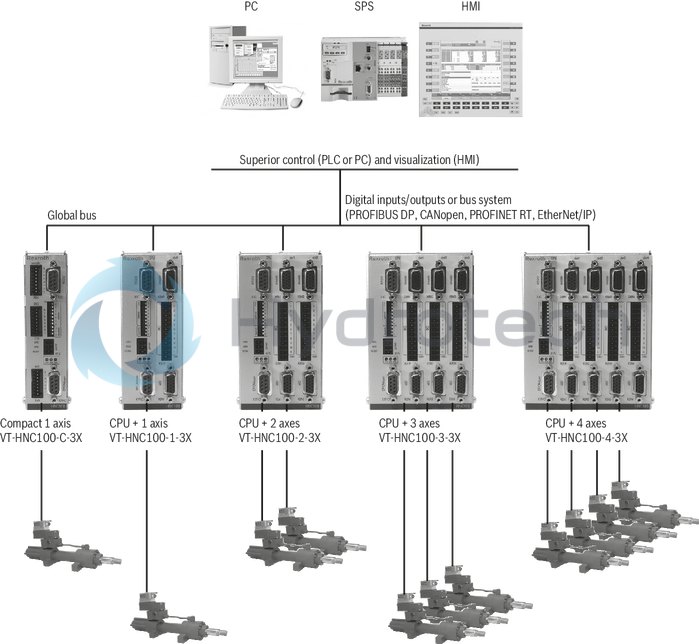
The Bosch Rexroth VT-HNC100-3-3X/P-I-00/000 (R901134620) is a state-of-the-art hydraulic drive controller designed for precision and flexibility in a variety of applications. This model is distinguished by its scalability in both hardware and software, making it suitable for different levels of complexity and performance requirements. The unit is robust and capable of remote operation, ensuring reliability even in challenging environments. The VT-HNC100-3-3X/P-I-00/000 excels in its versatility, supporting multiple control strategies including position, force, pressure control, and combinations such as alternating position-pressure or position-force controls. It also offers velocity control and path-dependent deceleration, as well as synchronism control following the master-slave principle or the mean value method. The controller can manage up to 4 axes, making it an all-in-one solution for complex hydraulic systems. For connectivity, this model includes various interfaces compatible with common fieldbuses and Ethernet protocols such as Sercos, PROFINET RT, and EtherNet/IP. These open interfaces ensure the controller can be seamlessly integrated into different automation environments. Actual value detection is comprehensive, with support for incremental positional transducers, absolute SSI positional transducers, analog signals from 0 to 10 V and 4 to 20 mA. Actuating variable outputs are available as either voltage or current outputs to suit various actuator types. The service interface comes standard with RS232 connectivity with an optional TCP/IP interface for enhanced communication options. Designed for component series X applications controlling from 1 to 4 axes, the VT-HNC100-3-3X/P-I-00/000 ensures best-in-class performance in hydraulic controllers by leveraging Bosch Rexroth's extensive expertise in hydraulics and motion control technology. Its engineering is further supported by powerful software tools like WinPed (not compatible with Windows CE), which simplifies setup and implementation of the controller in any application scenario.
Scalablein hardware and software (scalable, remote, robust)
The HNC100 is Rexroth's "all-rounder" in hydraulic drive control. Thanks to its distinct interface variety and free programmability, it fulfills various requirements and can be easily and flexibly integrated into any control architecture.
Consistent easy application.
Rexroth is the specialist for hydraulic systems – from open loop and closed loop control technology to drive technology. We provide you easily and quickly with our expertise. WinPed7 is the solution. The software tool ensures powerful engineering for an easy and quick implementation of your application.
Open to any solution
Regarding control solutions for hydraulic drives, Rexroth also consistently focus on open interfaces and programming standards. The Motion Controls support any commonly used field bus and Ethernet protocol and fit in seamlessly with various automation environments.
Best-in-class hydraulic controllers:
Rexroth has gathered unique knowledge of the interaction of hydraulics and Motion Control technology. Based on this knowledge, the control strategies for hydraulic and hybrid drives have been optimized and are represented in immediately usable software.
|
01 |
02 |
03 |
04 |
05 |
06 |
07 |
||||||
|
VT-HNC100 |
– |
– |
3X |
/ |
– |
– |
/ |
|
01 |
VT-HNC100 |
Serial unit |
|
02 |
Version Compact for 1 axis |
C |
|
Version for 1 hydraulic axis |
1 |
|
|
Versions for 2 hydraulic axes |
2 |
|
|
Versions for 3 hydraulic axes |
3 |
|
|
Versions for 4 hydraulic axes |
4 |
|
|
03 |
Component series 30 ... 39 (30 ... 39: unchanged technical data and pin assignment) |
3X |
|
Bus connection 2) |
||
|
04 |
PROFIBUS DP |
P |
|
CANopen |
C |
|
|
PROFINET RT (not in connection with Compact version) |
N |
|
|
EtherNet/IP (not in connection with Compact version) |
E |
|
|
Position transducer |
||
|
05 |
Incremental/SSI (not in connection with Compact version) |
I |
|
SSI (only in connection with Compact version) |
S |
|
|
06 |
no fitting |
00 |
|
TCP/IP 1) |
E0 |
|
|
Option |
||
|
07 |
without synchronism |
G00 |
|
Synchronism 2-axis version |
G02 |
|
|
Synchronism 3-axis version |
G03 |
|
|
Synchronism 4-axis version |
G04 |
|
| 1) Only specify "E0" if the Ethernet service interface is desired for "PROFIBUS DP" | |
| 2) Versions without bus connections are not available. |
General
|
Type / version |
VT-HNC100-C-3X | VT-HNC100-1-3X | VT-HNC100-2-3X | VT-HNC100-3-3X | VT-HNC100-4-3X | |
|
Component series |
3X | |||||
Voltage supply
|
Type / version |
VT-HNC100-C-3X | VT-HNC100-1-3X | VT-HNC100-2-3X | VT-HNC100-3-3X | VT-HNC100-4-3X | ||
|
Operating voltage 1) |
UB |
18 to 30 VDC, residual ripple < 1.5 V | |||||
|
Current consumption at 24 VDC |
I |
approx. 500 mA | 1 to 4 A (depending on the HNC variant and the also supplied components) | ||||
| 1) | If a 24 V encoder supply is implemented directly via the VT-HNC100...3X (supply voltage is looped in), the encoder specification has to be observed. |
Analog inputs (AI)
|
Type / version |
VT-HNC100-C-3X | |||
|
Voltage input (reference to AGND - Analog ground) |
Channel number |
1 | ||
|
Input voltage |
UE |
max. +12 V to –12 V (+10 V to –10 V measurable) | ||
|
Input resistance |
RE |
200 kΩ ± 5 % | ||
|
Resolution |
5 mV | |||
|
Non-linearity |
% |
< 0.2 | ||
|
Calibration tolerance, max. 1) |
40 mV (with factory settings) | |||
|
Current inputs |
Channel number |
2 | ||
|
Input current |
IE |
4 mA to 20 mA | ||
|
Input resistance |
RE |
225 Ω at 20 °C (100 Ω measuring resistance) | ||
|
Leakage current |
IV |
0.1 to 0.4 % (with 100 Ω between pin 2 or pin 3 (Cin1+ or Cin2+) and "AGND" | ||
|
Resolution |
5 μA | |||
|
Voltage supply for analog sensors via VT-HNC100-C-3X |
UB at X2A, pin 7 (+24 Vsens) | |||
| 1) | If the factory settings are insufficient, the measurement technology can be calibrated on site via software in a system-specific way. |
Analog inputs (AI) per axis electronics
|
Type / version |
VT-HNC100-1-3X | VT-HNC100-2-3X | VT-HNC100-3-3X | VT-HNC100-4-3X | |||
|
Voltage inputs (differential inputs) |
Channel number |
2 | |||||
|
Input voltage |
UE |
max. +12 V to –12 V (+10 V to –10 V measurable) | |||||
|
Input resistance |
RE |
200 kΩ ± 5 % | |||||
|
Resolution |
5 mV | ||||||
|
Non-linearity |
% |
< 0.2 | |||||
|
Calibration tolerance, max. 1) |
40 mV (with factory settings) | ||||||
|
Current inputs |
Channel number |
2 | |||||
|
Input current |
IE |
4 mA to 20 mA | |||||
|
Input resistance |
RE |
350 Ω at 20 °C (100 Ω measuring resistance) | |||||
|
Leakage current |
IV |
0.1 to 0.4 % | |||||
|
Resolution |
5 μA | ||||||
|
Voltage supply for analog sensors via VT-HNC100…3X |
U |
UB at X2A1 to X2A4, pin 14 (+24 Vsens) | |||||
| 1) | If the factory settings are insufficient, the measurement technology can be calibrated on site via software in a system-specific way. |
Digital inputs (DI)
|
Type / version |
VT-HNC100-C-3X | VT-HNC100-1-3X | VT-HNC100-2-3X | VT-HNC100-3-3X | VT-HNC100-4-3X | ||
|
Switching inputs (DI) |
Number |
4 | 11 | ||||
|
Logic level |
log 0 (low) ≤ 5 V; log 1 (high) ≥ 10 V to UB, Ie = 20 mA at UB = 24 V | ||||||
|
Connection |
flexible conductor up to 1.5 mm2 | ||||||
|
Reference potential for all signals |
DGND | ||||||
Analog outputs (AO)
|
Type / version |
VT-HNC100-C-3X | |||
|
Voltage outputs |
Channel number |
2 | ||
|
Output voltage, normalized |
Unorm |
–10 V to +10 V (max. –10.7 V to +10.7 V) | ||
|
Output current, max. |
Imax |
± 10 mA | ||
|
Load, min. |
Rmin |
kΩ |
1 | |
|
Resolution |
1.25 mV | |||
|
Non-linearity |
in the range –9.5 V to +9.5 V |
% |
< 0.1 | |
|
in the range –10 V to –9.5 V and +9.5 V to +10 V |
% |
< 0.2 | ||
Analog outputs (AO) per axis electronics
|
Type / version |
VT-HNC100-1-3X | VT-HNC100-2-3X | VT-HNC100-3-3X | VT-HNC100-4-3X | |||
|
Analog outputs (AO: 1) per axis electronics 1) |
2 | ||||||
|
Non-linearity |
in the range –9.5 V to +9.5 V |
% |
< 0.1 | ||||
|
in the range –10 V to –9.5 V and +9.5 V to +10 V |
% |
< 0.2 | |||||
|
Voltage output |
Output voltage, normalized |
Unorm |
–10 V to +10 V (max. –10.7 V to +10.7 V) | ||||
|
Output current, max. |
Imax |
± 10 mA | |||||
|
Load, min. |
Rmin |
kΩ |
1 | ||||
|
Residual ripple |
±60 mV (without noise) | ||||||
|
Resolution |
1.25 mV | ||||||
|
Current output |
Output current, normalized |
Inorm |
4 mA to 20 mA | ||||
|
Load, max. |
Rmax |
Ω |
500 | ||||
|
Resolution |
0.625 μA | ||||||
| 1) | Configurable as current or voltage output. Axis electronics slot 1 and axis electronics slot 2 feature two voltage outputs Vout1 and Vout2. Axis electronics slot 3 and axis electronics slot 4 feature one voltage output Vout1. |
Digital outputs (DO)
|
Type / version |
VT-HNC100-C-3X | VT-HNC100-1-3X | VT-HNC100-2-3X | VT-HNC100-3-3X | VT-HNC100-4-3X | ||
|
Switching outputs (DO) |
Number |
2 | 11 | ||||
|
Logic level |
log 0 (low) ≤ 2 V; log 1 (high) ≤ UB; Imax = 20 mA, maximum load capacity C = 0.047 μF | ||||||
|
Connection |
flexible conductor up to 1.5 mm2 | ||||||
|
Reference potential for all signals |
DGND | ||||||
Digital position transducers (encoders):
|
Type / version |
VT-HNC100-C-3X | |||
|
SSI transducer 1) |
Coding |
Gray code | ||
|
Data width |
adjustable up to max. 28 bit | |||
|
Line receiver/driver |
RS485 | |||
|
Voltage supply via VT-HNC100-C-3X |
U |
UB | ||
|
Reference potential for all signals |
EGND | |||
| 1) | Due to the higher control quality, an SSI transducer with clock synchronization should be used |
Digital position transducers (encoders) per axis electronics
|
Type / version |
VT-HNC100-1-3X | VT-HNC100-2-3X | VT-HNC100-3-3X | VT-HNC100-4-3X | ||||
|
Incremental transducer with TTL output |
Input voltage |
log 0 |
0 to 1 V | |||||
|
log 1 |
2.8 to 5.5 V | |||||||
|
Input current |
log 0 |
-0.8 mA (with 0 V) | ||||||
|
log 1 |
0.8 mA (with 5 V) | |||||||
|
Frequency, max. related to Ua1 |
fmax |
kHz |
250 | |||||
|
Voltage supply for incremental transducers via VT-HNC100…3X |
U |
5.25 V ±1 %, max. 400 mA total current over all axes at X8M1 to X8M4, Pin 12 (+5 Venc) | ||||||
|
SSI transducer 1) |
Coding |
Gray code | ||||||
|
Data width |
adjustable up to max. 28 bit | |||||||
|
Line receiver/driver |
RS485 | |||||||
|
Voltage supply for SSI transducers via VT-HNC100…3X |
U |
UB at X8M1 to X8M4, pin 14 (+24 Venc) | ||||||
|
Reference potential for all signals |
EGND | |||||||
| 1) | Due to the higher control quality, an SSI transducer with clock synchronization should be used |
Other information
|
Type / version |
VT-HNC100-C-3X | VT-HNC100-1-3X | VT-HNC100-2-3X | VT-HNC100-3-3X | VT-HNC100-4-3X | ||
|
Processor |
32 bit power PC | ||||||
|
Interface for WIN-PED 6, WIN-PED7 |
RS232 | ||||||
|
Bus interface |
PROFIBUS DP (max. 12 MBaud acc. to IEC 61158), CANopen | RS232, optional TCP/IP | |||||
| PROFIBUS DP (max. 12 MBaud acc. to IEC 61158), CANopen, PROFINET RT, EtherNet/IP | |||||||
|
Installation |
Top hat rail TH 35-7.5 or TH 35-15 according to EN 60715 | ||||||
|
Admissible operating temperature range |
ϑ |
°C |
0 … +50 | ||||
|
Storage temperature range |
ϑ |
°C |
-20 … +70 | ||||
|
Protection class according to EN 60529:1991 |
IP 20 | ||||||
|
Weight |
m |
g |
440 | 585 | 690 | 850 | 960 |
|
m |
223 g 1) | ||||||
|
CE conformity |
See features | ||||||
| 1) | with Ethernet, in addition |
PROFINET RT, EtherNet/IP
|
Type / version |
VT-HNC100-1-3X | VT-HNC100-2-3X | VT-HNC100-3-3X | VT-HNC100-4-3X | |
|
Minimum cycle time |
ms |
2 | |||
|
Size of the cyclic I/O data, max. |
992 byte (max. 496 byte per direction) | ||||
|
Transmission rate |
100 Mbits/s, full-duplex | ||||
For applications outside these parameters, please consult us!
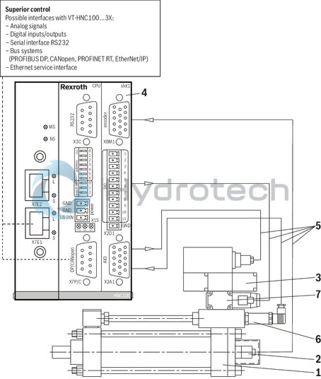
System overview (example)
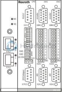
System overview, interfaces (example)
|
1 |
Differential cylinder |
|
2 |
integrated position measurement system |
|
3 |
Proportional servo valve with integrated control electronics |
|
4 |
VT-HNC100-1-3X/N... |
|
5 |
Connection cable |
|
6 |
Pressure transducer |
|
7 |
Sandwich plate shut-off valve (with connector switching amplifier) |
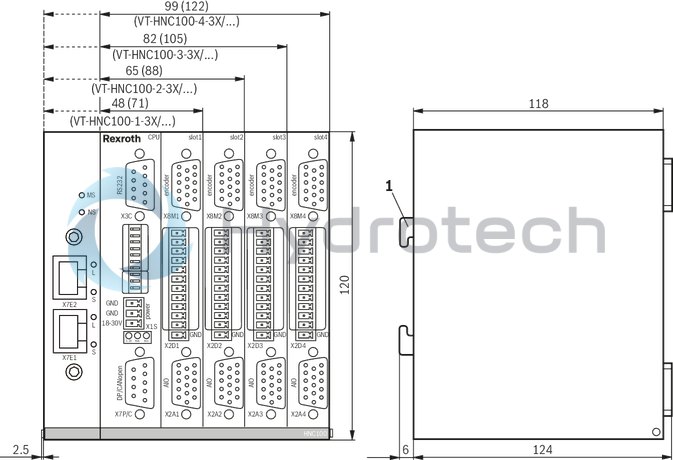
Dimensions in mm
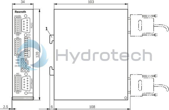
|
1 |
Installation on top hat rail TH 35-7.5 or TH 35-15 according to EN 60715 |
Dimensions in mm
|
1 |
Installation on top hat rail TH 35-7.5 or TH 35-15 according to EN 60715 |