

BOSCH REXROTH
R901133616
$14,229.94 USD
- BOSCH REXROTH
- Material:R901133616
- Model:4WS2EM10-5X/45B11XHET315K31DV
Quantity in stock: 0
The Bosch Rexroth 4WS2EM10-5X/45B11XHET315K31DV (R901133616) is an advanced stage directional servo valve designed to precisely control position, force, pressure, or velocity in hydraulic systems. This model is particularly suitable for applications requiring high levels of accuracy and responsiveness. It operates based on the electromechanical conversion of an electrical input signal into mechanical movement via a torque motor, which employs a nozzle flapper plate system and a control spool within a sleeve. The servo valve's operation involves the torque motor generating a force that moves the flapper plate, creating a pressure differential across the spool. This action connects the pressure port to one actuator port while simultaneously connecting the other actuator port to the return flow port. The spool's position is regulated by mechanical feedback through a bending spring until equilibrium is reached between electromagnetic and feedback torque, resulting in zero pressure differential at the nozzle flapper plate system. Designed for subplate mounting with an ISO-compliant porting pattern and capable of functioning as both 4-way and 3-way versions, this valve features dry control motor technology that prevents contamination of solenoid gaps by hydraulic fluid. It also includes wear-free spool feedback elements and external control electronics for precise actuation. The valve is adjusted and tested for optimal performance. The 4WS2EM10-5X/45B11XHET315K31DV can operate at maximum pressures up to bar and handle maximum flow rates of l/min. Its construction includes gap seals in pressure chambers to avoid seal ring wear and an accessible filter for easy maintenance of the first stage. The model is also designed for use in potentially explosive areas classified under EU Explosion Protection Directive IIG with ExiaIICTGa type protection according to EN standards. Overall, this Bosch Rexroth servo valve represents a sophisticated solution for dynamic hydraulic control tasks where precision and reliability are paramount.
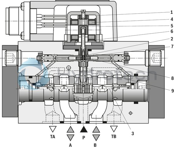
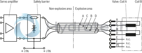
Valves of the type 4WS2EM are electrically operated, 2-stage directional servo valves with porting pattern according to ISO 4401-05-05-0-05. They are mainly used to control position, force, pressure or velocity. These valves are made of an electro-mechanical converter (torque motor) (1), a hydraulic amplifier (principle: nozzle flapper plate) (2) and a control spool (3) in a sleeve (2nd Stage) which is connected with the torque motor via a mechanical feedback.
An electrical input signal at the coils (4) of the torque motor generates a force by means of a permanent magnet which acts on the armature (5), and in connection with a torque tube (6) results in a torque. This causes the flapper plate (7) which is connected to the torque tube (6) via a bolt to move from the central position between the two control nozzles (8), and a pressure differential is created across the front sides of the control spool (3). The pressure differential results in the spool changing its position, which results in the pressure port being connected to one actuator port and, at the same time, the other actuator port being connected to the return flow port.
The control spool is connected to the flapper plate or the torque motor by means of a bending spring (mechanical feedback) (9). The position of the spool is changed until the feedback torque across the bending spring and the electromagnetic torque of the torque motor are balanced and the pressure differential at the nozzle flapper plate system becomes zero.
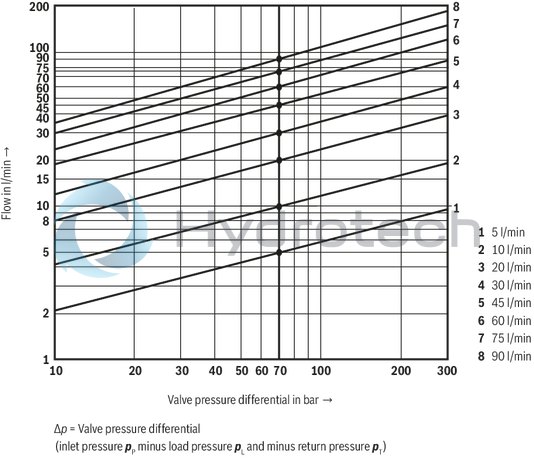
The stroke of the control spool and consequently the flow of the servo valve are regulated proportionally to the electrical input signal. It must be noted that the flow depends on the valve pressure drop.
External control electronics (separate order)
External control electronics (servo amplifier) serve the actuation of the valve, amplifying an analog input signal (command value) so that with the output signal, the servo valve is actuated in a flow-controlled form.
Typ 4WS2EM 10…XH
|
01 |
02 |
03 |
04 |
05 |
06 |
07 |
08 |
09 |
10 |
11 |
12 |
13 |
|||
|
4 |
WS2EM |
10 |
- |
5X |
/ |
B |
11 |
XH |
K31 |
V |
* |
|
01 |
4 main ports |
4 |
|
02 |
Electrically operated 2-stage servo valve in 4/3 directional design with mechanical feedback for external control electronics |
WS2EM |
|
03 |
Size 10 |
10 |
|
04 |
Component series 50 … 59 (50 … 59: unchanged installation and connection dimensions) |
5X |
|
Nominal flow 1) |
||
|
05 |
5 l/min |
5 |
|
10 l/min |
10 |
|
|
20 l/min |
20 |
|
|
30 l/min |
30 |
|
|
45 l/min |
45 |
|
|
60 l/min |
60 |
|
|
75 l/min |
75 |
|
|
90 l/min |
90 |
|
|
06 |
Valves for external control electronics: Coil no. 11 (30 mA / 85 Ω per coil) 2) |
11 |
|
Explosion protection |
||
|
07 |
"Type of protection ia", for details, please refer to the "information on explosion protection" |
XH |
|
Pilot oil supply and return 3) |
||
|
08 |
External pilot oil supply, external pilot oil return |
- |
|
Internal pilot oil supply, external pilot oil return |
E |
|
|
External pilot oil supply, internal pilot oil return |
T |
|
|
Internal pilot oil supply, internal pilot oil return (standard) |
ET |
|
|
Inlet pressure range to the 1st stage 4) |
||
|
09 |
10 … 210 bar |
210 |
|
10 … 315 bar |
315 |
|
|
Electrical connection |
||
|
10 |
Without mating connector, with connector 6) |
K31 |
|
Control spool overlap 5) |
||
|
11 |
0 ... 0,5 % positiv |
D |
|
0 ... 0,5% negativ |
E |
|
|
3 ... 5 % positiv |
C |
|
|
Seal material |
||
|
12 |
FKM seals, suitable for mineral oil (HL, HLP) according to DIN 51524 |
V |
|
13 |
Further details in the plain text |
* |
| 1) |
Rated flow The rated flow refers to a 100 % command value signal at 70 bar valve pressure differential (35 bar per control edge). The valve pressure differential must be regarded as reference. Other values result in the flow being changed. A possible rated flow tolerance of ±10 % must be taken into account (see flow/signal function under characteristic curves). |
| 2) |
External control electronics The actuating signal must be created from a flow-controlled output stage with a superimposed dither signal. Control electronics (servo amplifier), see electrical connection. |
| 3) |
Pilot oil Care should be taken that the pilot pressure is as constant as possible. An external pilot control via port X is thus often advantageous. The valve can be operated with a higher pressure at X than at P in order to influence the dynamics in a positive form. Notice: The ports X and Y are also pressurized in case of "internal" pilot oil supply and return. |
| 4) |
Inlet pressure range Care should be taken that the system pressure is as constant as possible. Pilot pressure range: 10 ... 210 bar or 10 ... 315 bar. With regard to the dynamics, the frequency response dependency must be observed within the admissible pressure range. |
| 5) |
Spool overlap The control spool overlap is specified in % of the nominal control spool stroke. |
| 6) | Mating connectors, separate order, see "Accessories" |
For applications outside these parameters, please consult us!
general
|
Type |
4WS2EM 10...XH | ||
|
Size |
10 | ||
|
Component series |
5X | ||
|
Porting pattern |
ISO 4401-05-05-0-05 | ||
|
Installation position |
Any - ensure that during start-up of the system, the valve issupplied with sufficient pressure (≥ 10 bar)! | ||
|
Surface protection |
Valve body, cover, filter screw |
nitro-carburated | |
|
Cap |
anodized | ||
|
Storage temperature range |
°C |
+5 … +40 | |
|
Weight |
kg |
3.56 | |
|
Ambient temperature range |
°C |
-20 … +60 | |
hydraulic
|
Type |
4WS2EM 10...XH | |||
|
Maximum operating pressure |
bar |
315 | ||
|
Maximum operating pressure |
Port A |
bar |
315 | |
|
Port B |
bar |
315 | ||
|
Port P |
bar |
315 | ||
|
Operating pressure range |
Pilot control stage |
Pilot oil supply |
bar |
10 ... 210; 10 ... 315 |
|
Maximum return flow pressure |
Port T |
Pilot oil return, external |
bar |
315 |
|
Pilot oil return, internal |
bar |
Pressure peaks <100 admissible | ||
|
Port Y |
bar |
Pressure peaks < 100, static < 10 | ||
|
Hydraulic fluid |
Mineral oil (HL, HLP) according to DIN 51524; Ignition temperature > 150 °C |
|||
|
Hydraulic fluid temperature range |
°C |
-15 … +60 | ||
|
preferably |
°C |
+40 … +50 | ||
|
Maximum admissible degree of contamination of the hydraulic fluid, cleanliness class according to ISO 4406 (c) 1) |
Class 18/16/13 | |||
|
Viscosity range |
mm²/s |
15 … 380 | ||
|
preferably |
mm²/s |
30 … 45 | ||
|
Feedback system |
mechanical | |||
|
Hysteresis (dither-optimized) |
% |
≤ 1.5 | ||
|
Range of inversion (dither-optimized) |
% |
≤ 0.3 | ||
|
Response sensitivity (dither-optimized) |
% |
≤ 0.2 | ||
|
Zero adjustment flow over the entire operating pressure range 2) |
% |
≤ 3 | ||
|
Zero shift upon change of |
Hydraulic fluid temperature |
%/20° C |
≤ 1 | |
|
Ambient temperature |
%/20° C |
≤ 1 | ||
|
Operating pressure 80 … 120 % of pP 3) |
%/100 bar |
≤ 2 | ||
|
Return flow pressure 0 … 10 % of pP 3) |
%/bar |
≤ 1 | ||
| 1) | The cleanliness classes specified for the components must be adhered to in hydraulic systems. Effective filtration prevents faults and simultaneously increases the life cycle of the components. For the selection of the filters, see www.boschrexroth.com/filter. |
| 2) | long-term ≤ 5% |
| 3) | pP = operating pressure in bar |
hydraulic
|
Rated flow (tolerance ±10 % with valve pressure differential ∆p = 70 bar (35 bar/edge)) 1) 2) |
l/min |
5 | 10 | 20 | 30 | 45 | 60 | 75 | 90 |
|
Zero flow (with spool overlap "E", measured without dither signal) 3) 4) |
l/min |
 x = 0.7 x = 0.7
|
x = 0.9
|
x = 1.2
|
x = 1.2
|
x = 1.2
|
x = 1.5
|
x = 1.5
|
x = 1.7
|
|
Maximum control spool stroke at mechanical end position (in case of error) related to nominal stroke |
120 ... 170 % | 120 ... 150 % | |||||||
|
Pressure amplification with 1 % control spool stroke change (from the hydraulic zero point) 4) 5) |
% |
≥ 30 | ≥ 60 | ≥ 80 | |||||
| 1) | Tolerance ±10 % with valve pressure differential Δp = 70 bar |
| 2) | qv nom = rated flow in l/min |
| 3) | qV,L = zero flow in l/min |
| 4) | pP = operating pressure in bar |
| 5) | of pp with 1 % spool stroke change (from the hydraulic zero point) |
Notice:
The specified technical data were measured with HLP32 and ϑOil = 40 ±5 °C.
electrical
|
Type |
4WS2EM 10...XH | ||
|
Size |
10 | ||
|
Rated current per coil |
mA |
30 | |
|
Protection class according to EN 60529 |
IP65 (with mating connector mounted and locked) | ||
|
Type of signal |
analog | ||
|
Resistance per coil |
Ω |
85 | |
|
Inductivity 1) |
Parallel connection |
H |
0.25 |
| 1) | With 60 Hz and 100% rated current |
Notice:
In case of control using non-Rexroth amplifiers, we recommend a superimposed dither signal.
Information on explosion protection
|
Area of application according to directive 2014/34/EU |
II 1G | ||
|
Valve solenoid type of protection according to EN 60079-0 / EN 60079-11 |
Ex ia IIC T4 Ga | ||
|
Power supply of the valve only by certified, intrinsically safe electric circuits with the following maximum values |
Admissible voltage Umax |
V |
9.3 |
|
Admissible current Imax |
mA |
390 | |
|
Admissible power Pmax |
mW |
907 | |
Conditions for use in zone 0
The valve cap is made of die-cast aluminum. For the use as a device of category 1 in zone 0, the valve cap must be protected in a way that ensures that even in case of rare operating failures, no explosive sparks from friction, impact or grinding can occur. Notice: The ignition temperature of the hydraulic fluid used must be at least 150 °C.
Required clearance area for bursting protection
The indicated clearance area for bursting protection (see "Dimensions") must be kept clear so that in the error case, overpressure can escape from the valve cap through the blanking plug.(measured with HLP32, ϑOil =40 ±5 °C)
Flow/load function (tolerance ±10 %) with 100 % command value signal
Notice: Observe the flow values in max. command value range (see tolerance field of the flow/signal function)
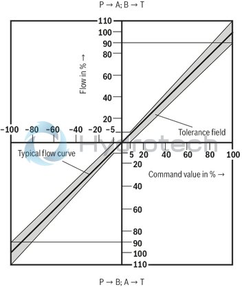
Tolerance field of the flow/signal function with constant valve pressure differential Δp
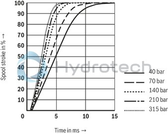
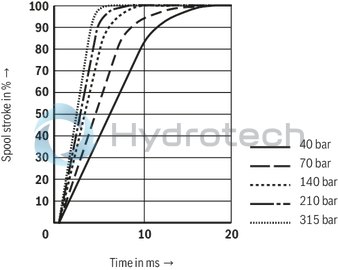
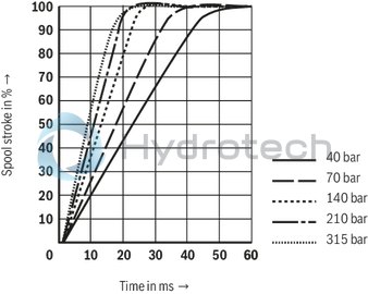
Transition function with pressure rating 315 bar, step response without flow (measured with safety barrier, information on the safety barrier see electrical connection)
Rated flow 5, 10, 20 l/min
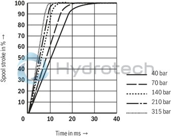
Transition function with pressure rating 315 bar, step response without flow (measured with safety barrier, information on the safety barrier see electrical connection)
Rated flow 30 l/min
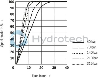
Transition function with pressure rating 315 bar, step response without flow (measured with safety barrier, information on the safety barrier see electrical connection)
Rated flow 45 l/min
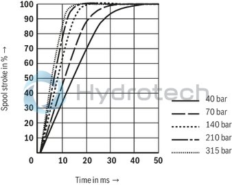
Transition function with pressure rating 315 bar, step response without flow (measured with safety barrier, information on the safety barrier see electrical connection)
Rated flow 60 l/min
Transition function with pressure rating 315 bar, step response without flow (measured with safety barrier, information on the safety barrier see electrical connection)
Rated flow 75 l/min
Transition function with pressure rating 315 bar, step response without flow (measured with safety barrier, information on the safety barrier see electrical connection)
Rated flow 90 l/min
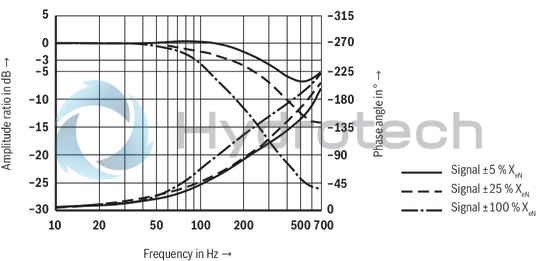
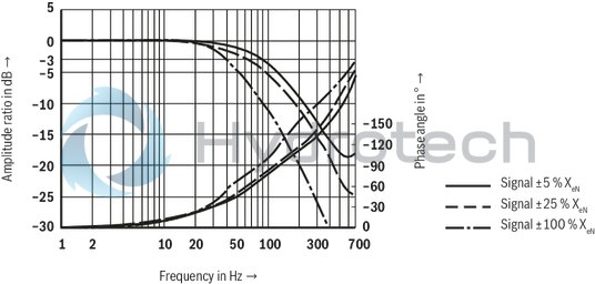
Frequency response with pressure rating 315 bar, stroke frequency without flow (measured with safety barrier, information on the safety barrier see electrical connection)
Rated flow 5, 10, 20 l/min
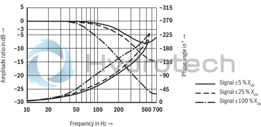
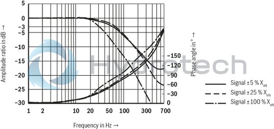
Frequency response with pressure rating 315 bar, stroke frequency without flow (measured with safety barrier, information on the safety barrier see electrical connection)
Rated flow 30 l/min
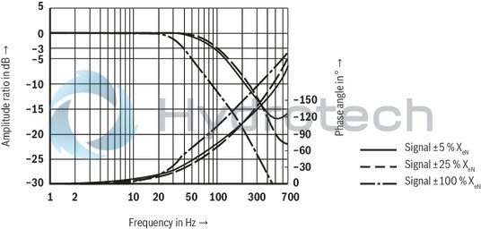
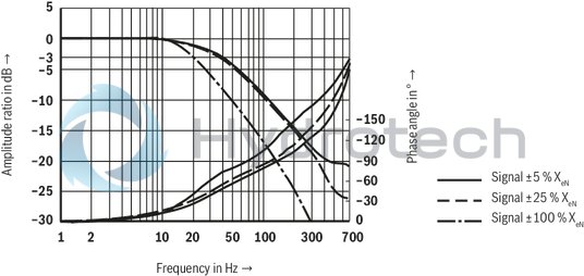
Frequency response with pressure rating 315 bar, stroke frequency without flow (measured with safety barrier, information on the safety barrier see electrical connection)
Rated flow 45 l/min
Frequency response with pressure rating 315 bar, stroke frequency without flow (measured with safety barrier, information on the safety barrier see electrical connection)
Rated flow 60 l/min
Frequency response with pressure rating 315 bar, stroke frequency without flow (measured with safety barrier, information on the safety barrier see electrical connection)
Rated flow 75 l/min
Frequency response with pressure rating 315 bar, stroke frequency without flow (measured with safety barrier, information on the safety barrier see electrical connection)
Rated flow 90 l/min
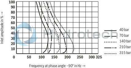
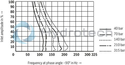
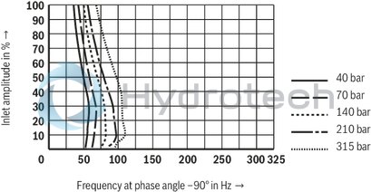
Dependency of the frequency f at -90° of the operating pressure p and the inlet amplitude (measured with safety barrier, information on the safety barrier see electrical connection)
Rated flow 5, 10, 20 l/min
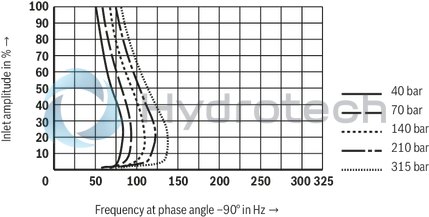
Dependency of the frequency f at -90° of the operating pressure p and the inlet amplitude (measured with safety barrier, information on the safety barrier see electrical connection)
Rated flow 30 l/min
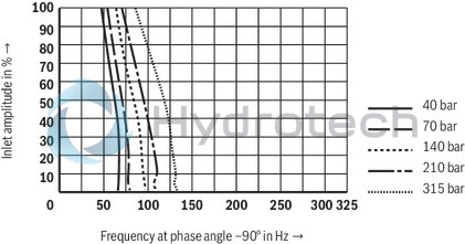
Dependency of the frequency f at -90° of the operating pressure p and the inlet amplitude (measured with safety barrier, information on the safety barrier see electrical connection)
Rated flow 45 l/min
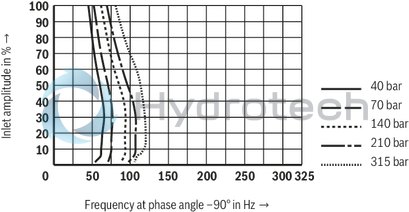
Dependency of the frequency f at -90° of the operating pressure p and the inlet amplitude (measured with safety barrier, information on the safety barrier see electrical connection)
Rated flow 60 l/min
Dependency of the frequency f at -90° of the operating pressure p and the inlet amplitude (measured with safety barrier, information on the safety barrier see electrical connection)
Rated flow 75 l/min
Dependency of the frequency f at -90° of the operating pressure p and the inlet amplitude (measured with safety barrier, information on the safety barrier see electrical connection)
Rated flow 90 l/min
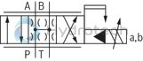
External control electronics (separate order)
|
Servo amplifier |
Modular design analog |
Type VT 11021 according to data sheet 29743 |
|
Recommended safety barrier |
One-channel |
Company Stahl, type 9001/02-093-390-101 |
|
WARNING – Explosion hazard |
||
The coils may only be connected in parallel! The electrical control with plus (+) at A and B and minus (-) at C and D provides for the direction of flow P → A and B → T. Reverse electrical control provides for the direction of flow P → B and A → T. The pins E, F and PE at the connector are not connected. Notice: Only use approved cables and lines for intrinsically safe electric circuits.
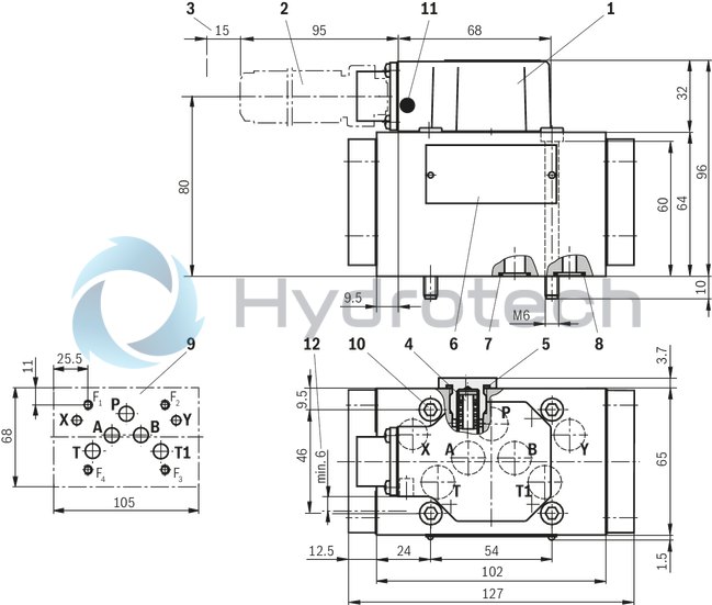
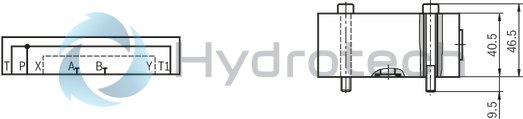
Dimensions in mm
|
|
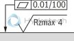
Required surface quality of the valve contact surface |
|
1 |
Cap |
|
2 |
Mating connectors, separate order, see "Accessories" |
|
3 |
Space required for removing the mating connector, additionally observe the bending radius of the connection line |
|
4 |
Exchangeable filter element with seals Material no.: R961001950 |
|
5 |
Profile seal for filter screw M16 x 1.5; part of item 4 |
|
6 |
Name plate |
|
7 |
Identical seal rings for ports P, A, B, T and T1 |
|
8 |
Identical seal rings for ports X and Y |
|
9 |
Machined valve contact surface; Porting pattern according to ISO 4401-05-05-0-05 |
|
10 |
Valve mounting screws (included in the scope of delivery) |
|
11 |
Bursting protection |
|
12 |
Clearance area for bursting protection |
Subplates (separate order)
with porting pattern according to ISO 4401-05-05-0-05 see data sheet 45100.
Notice:
Subplates are no components in the sense of directive 2014/34/EU and can be used after the manufacturer of the overall system has conducted an assessment of the risk of ignition. The "G...J3" versions are free from aluminum and/or magnesium and galvanized.
Valve amplifiers for servo-valves
VT 11021-1X
Valve amplifiers for servo-valves
VT 11021-1X
Component series 1X Analog, Modular design For valves: 4WS2EM 6-2X, 4WS2EM 10-5X and 4WS2EM 16-2XData sheet
Configurator / CAD
Spare parts & repair
Mating connectors for valves with round connector, 6-pole + PE
7P Z31
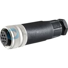
Mating connectors for valves with round connector, 6-pole + PE
7P Z31
For valves with round connector according to EN 175201-804, 6-pole + PE as well as 6-pole, compatible with VG 95328Data sheet
Spare parts & repair
Flushing plate with porting pattern according to ISO 4401-05-05-0-05
(dimensions in mm)
Ordering code and further information:
Type HSA 10 B019-3X/V00 Material number: R900912450 Porting pattern according to ISO 4401-05-05-0-05 Weight 2 kg Identical seal rings for ports P, A, B, T and T1 Identical seal rings for ports X and Y Mounting screws (included in the scope of delivery)For reasons of stability, exclusively the following mounting screws are to be used:
4 hexagon socket head cap screws ISO 4762-M6x50-10.9-flZn-240h-L
(Friction coefficient 0.09 … 0.14)
Notice:
Before assembly and operation, please observe the information in the operating instructions.