


BOSCH REXROTH
R901108990
$442.51 USD
- BOSCH REXROTH
- Material:R901108990
- Model:4WE6J7X/HG24N9K4/B10
Quantity in stock: 0
The Bosch Rexroth 4WE6J7X/HG24N9K4/B10 (R901108990) is a high-performance directional spool valve designed for controlling the start, stop, and direction of fluid flow within a hydraulic system. This model features wet-pin DC solenoids that actuate the control spool, allowing for precise operation. The solenoids generate force that moves the control spool from its rest position to an activated state, enabling the desired flow direction as indicated by the valve's symbol. Constructed with a durable housing, it incorporates one or two solenoids depending on the configuration, a control spool, and return springs. When not energized, these return springs hold the control spool in its central or initial position. The inclusion of a manual override offers flexibility by permitting manual operation of the control spool without requiring solenoid activation. The 4WE6J7X/HG24N9K4/B10 valve is engineered to maintain efficient functionality; it is crucial that the pressure chamber for the solenoid is filled with oil to ensure optimal performance. Additionally, this model allows for easy maintenance as the solenoid coil can be rotated and replaced without opening the pressure-tight chamber. For electrical connections, this valve features individual connections and boasts a concealed manual override feature. It adheres to porting patterns according to DIN form A standards. The size and component series X indicate compatibility with various hydraulic systems while supporting maximum operating pressures up to bar levels and accommodating maximum flow rates measured in liters per minute (l/min). This directional valve is an essential component for hydraulic applications requiring reliable and precise flow direction control within their operations.
Directional valves of type WE are solenoid-actuated directional spool valves. They control the start, stop and direction of a flow.
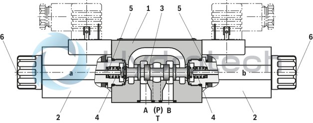
The directional valves basically consist of the housing (1), one or two solenoids (2), the control spool (3), and one or two return springs (4). In the de-energized condition, control spool (3) is held in the central position or in the initial position by the return springs (4). The control spool (3) is actuated by wet-pin solenoids (2).
To ensure proper functioning, make sure that the pressure chamber of the solenoid is filled with oil!
The force of the solenoid (2) acts via the plunger (5) on the control spool (3) and pushes the latter from its rest position to the required end position. In this way, the required direction of flow according to the symbol is released. After de-excitation of the solenoid (2), the return spring (4) pushes the control spool (3) back to its rest position.
The manual override (6) allows control spool (3) to be moved without solenoid energization.
Type 4WE 6 E7X/H…
|
01 |
02 |
03 |
04 |
05 |
06 |
07 |
08 |
09 |
10 |
11 |
12 |
||
|
WE |
6 |
7X |
/ |
H |
N9 |
/ |
* |
|
01 |
3 main ports |
3 |
|
4 main ports |
4 |
|
|
02 |
Directional valve |
WE |
|
03 |
Size 6 |
6 |
|
04 |
Symbols e. g. D, E etc.; possible design see Symbols |
|
|
05 |
Component series 70 … 79 (70 … 79: unchanged installation and mounting dimensions) |
7X |
|
06 |
With spring return |
no code |
|
Without spring return with detent |
OF1) |
|
|
07 |
Standard solenoid wet (wet-pin) |
H |
|
08 |
Direct voltage 12 V |
G12 |
|
Direct voltage 24 V |
G24 |
|
|
09 |
With concealed manual override |
N9 |
|
Electrical connection |
||
|
10 |
Individual connection |
|
|
Without mating connector, with connector DIN EN 175301-803 |
K42) |
|
|
Without mating connector, with connector AMP Junior-Timer |
C4Z 2) |
|
|
Seal material |
||
|
11 |
NBR seals |
no code |
|
Observe compatibility of seals with hydraulic fluid used. (Other seals upon request) |
||
|
12 |
Further details in the plain text |
* |
| 1) Only symbol D | |
| 2) Mating connectors, separate order, see data sheet 08006. |
Preferred types and standard units arecontained in the EPS (standard price list).
general
|
Size |
6 | ||
|
Weight (approx.) |
Valve with one solenoid |
kg |
1.25 |
|
Valve with two solenoids |
kg |
1.6 | |
|
Installation position |
any | ||
|
Ambient temperature range |
°C |
-30 … +50 | |
hydraulic
|
Size |
6 | ||
|
Maximum operating pressure |
Port P |
bar |
315 |
|
Port A |
bar |
315 | |
|
Port B |
bar |
315 | |
|
Port T 1) |
bar |
160 | |
|
Maximum flow |
l/min |
60 | |
|
Hydraulic fluid |
see table | ||
|
Hydraulic fluid temperature range |
°C |
-30 … +80 | |
|
Viscosity range |
mm²/s |
2.8 … 500 | |
|
Maximum admissible degree of contamination of the hydraulic fluid 2) |
Class 20/18/15 according to ISO 4406 (c) | ||
| 1) | With symbols A and B, port T must be used as leakage oil connection if the operating pressure exceeds the admissible tank pressure. |
| 2) | The cleanliness classes specified for the components must be adhered to in hydraulic systems. Effective filtration prevents faults and simultaneously increases the life cycle of the components. For the selection of the filters, see www.boschrexroth.com/filter. |
|
Hydraulic fluid |
Classification |
Suitable sealing materials |
Standards |
|
|
Mineral oils |
HL, HLP, HLPD, HVLP, HVLPD |
NBR, FKM |
DIN 51524 |
|
|
Bio-degradable |
Insoluble in water |
HETG |
NBR, FKM |
VDMA 24568 |
|
HEES |
FKM |
|||
|
Soluble in water |
HEPG |
FKM |
VDMA 24568 |
|
|
Containing water |
Water-free |
HFDU, HFDR |
FKM |
ISO 12922 |
|
Containing water |
HFC (Fuchs Hydrotherm 46M, Petrofer Ultra Safe 620 ) |
NBR, HNBR |
ISO 12922 |
|
|
Important information on hydraulic fluids! For further information and data on the use of other hydraulic fluids, please refer to data sheet 90220 or contact us! There may be limitations regarding the technical valve data (temperature, pressure range, life cycle, maintenance intervals, etc.)! The flash point of the hydraulic fluid used must be 40 K higher than the maximum solenoid surface temperature. Flame-resistant – containing water: Maximum pressure differential per control edge 50 bar. Pressure pre-loading at the tank port >20% of the pressure differential; otherwise, increased cavitation Life cycle compared to operation with mineral oil HL, HLP 50 to 100 % Bio-degradable: When using bio-degradable hydraulic fluids that are zinc-solving, zinc may accumulate in the fluid (700 mg zinc per pole tube) |
||||
Notices!
Only actuate the manual override using a rounded tool (Ø3+1 mm) or special tool (separate order, material no. R900024943)! Actuation of the manual override only up to a tank pressure 50 bar. When the manual override is blocked, the actuation of the solenoid must be prevented! The simultaneous actuation of the solenoids must be prevented!In the electrical connection, the protective earthing conductor (PE, grounded) is to be connected in accordance with the stipulations.
electrical
|
Voltage type |
Direct voltage | ||
|
Available voltages |
V |
12 / 24 | |
|
Voltage tolerance (nominal voltage) |
% |
± 10 | |
|
Power consumption |
W |
26 | |
|
Duty cycle |
% |
100 | |
|
Maximum coil temperature 1) |
°C |
150 | |
|
Switching time according to ISO 6403 |
ON |
ms |
20 … 45 |
|
OFF |
ms |
10 … 25 | |
|
Maximum switching frequency |
1/h |
15000 | |
|
Protection class according to DIN EN 60529 |
IP65 (with mating connector mounted and locked) | ||
|
Insulation class VDE 0580 |
F | ||
| 1) | Due to the high surface temperatures of the solenoid coils >50 °C, the standards ISO 13732-1 and ISO 4413 must be adhered and the coils must be equipped with contact protection, if required. |
For applications outside these parameters, please consult us!
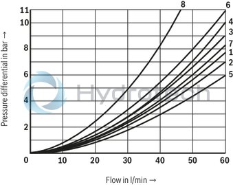
(measured with HLP46, ϑOil = 40 ±5 °C)
Δp-qV characteristic curves
|
7 |
Symbol "H" in central position P – T |
|
8 |
Symbol "G" in central position P – T |
|
Symbol |
Direction of flow |
|||
|
P-A |
P-B |
A-T |
B-T |
|
|
A, B |
3 |
3 |
– |
– |
|
C |
1 |
1 |
3 |
1 |
|
D, Y |
4 |
4 |
3 |
3 |
|
E |
3 |
3 |
1 |
1 |
|
J |
1 |
1 |
2 |
1 |
|
G |
6 |
6 |
7 |
7 |
|
H |
2 |
5 |
2 |
2 |
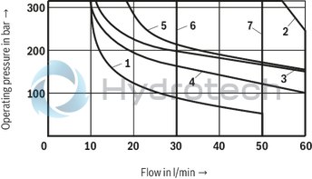
Switching power limits (measured with HLP46, ϑOil = 40 ±5 °C)
Notice!
The specified switching power limits are valid for use with two directions of flow (e. g. from P to A and simultaneous return flow from B to T).
Due to the flow forces acting within the valves, the admissible switching power limits may be considerably lower with only one direction of flow (e. g. from P to A while port B is blocked)!
In such use cases, please consult us!
The switching power limit was established while the solenoids were at operating temperature, at 10 % undervoltage and without tank preloading.
|
DC solenoid |
|
|
Characteristic curve |
Symbol |
|
1 |
A, B |
|
2 |
C, Y |
|
3 |
E |
|
4 |
J |
|
5 |
D |
|
6 |
G, H |
|
7 |
D/OF |
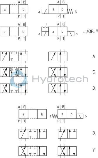
| 1) | Only symbol D |
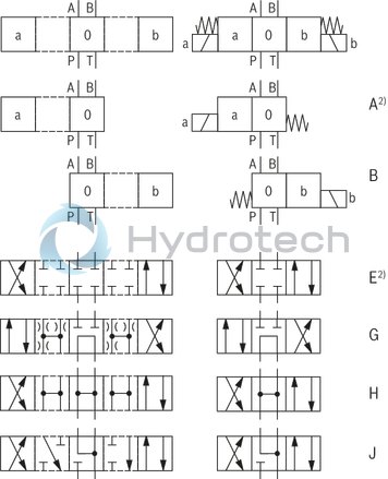
| 2)Example: Symbol E with switching position "a" Ordering code ..EA.. |
Version "K4"
Dimensions in mm
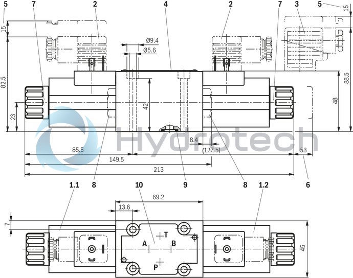
|
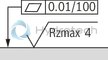
|
Required surface quality of the valve contact surface |
|
1.1 |
Solenoid “a” |
|
1.2 |
Solenoid “b” |
|
2 |
Mating connector without circuitry (separate order) |
|
3 |
Mating connector with circuitry (separate order) |
|
4 |
Name plate |
|
5 |
Space required to remove the mating connector |
|
6 |
Space required to remove the coil |
|
7 |
Mounting nut, MA = 4+1 Nm |
|
8 |
Plug screw for valve with one solenoid |
|
9 |
Identical seal rings for ports A, B, P, and T |
|
10 |
Porting pattern according to DIN 24340 form A |
Version "C4Z"
Dimensions in mm
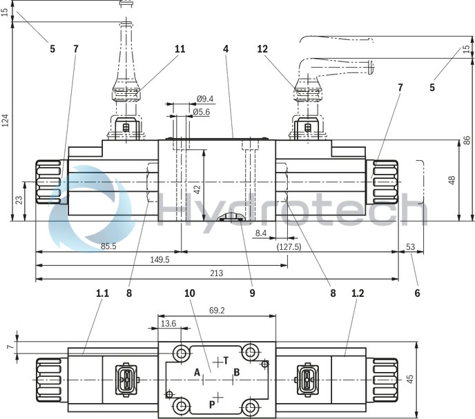
|
|
|
Required surface quality of the valve contact surface |
|
1.1 |
Solenoid “a” |
|
1.2 |
Solenoid “b” |
|
4 |
Name plate |
|
5 |
Space required to remove the mating connector |
|
6 |
Space required to remove the coil |
|
7 |
Mounting nut, MA = 4+1 Nm |
|
8 |
Plug screw for valve with one solenoid |
|
9 |
Identical seal rings for ports A, B, P, and T |
|
10 |
Porting pattern according to DIN 24340 form A |
|
11 |
Mating connector "Junior Timer", straight (separate order, see data sheet 08006) |
|
12 |
Mating connector "Junior Timer", angled (separate order, see data sheet 08006) |
Subplates according to data sheet 45052 (separate order)
G 341/01 (G1/4)
G 342/01 (G3/8)
G 502/01 (G1/2)
Valve mounting screws (separate order)
4 hexagon socket head cap screws ISO 4762 - M5 x 50 - 10.9-flZn-240h-L(friction coefficient μtotal = 0.09 to 0.14);
tightening torque MA = 7 Nm ± 10 %,
material no. R913000064
or
4 hexagon socket head cap screws ISO 4762 - M5 x 50 - 10.9with friction coefficient μtotal = 0.12 to 0.17 a
tightening torque MA = 8.1 Nm ± 10 % results
(not included in the Rexroth delivery range)
Mating connectors for valves with connector “K4”, without circuitry, standard
3P Z4
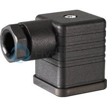
Mating connectors for valves with connector “K4”, without circuitry, standard
3P Z4
For valves with connector “K4” according to EN 175301-803 and ISO 4400, 2-pole + PE, “large cubic connector” Mating connectors for valves with one or two solenoids (individual connection)Data sheet
Spare parts & repair
Mating connectors for valves with connector “K4”, with indicator light
3P Z5L
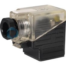
Mating connectors for valves with connector “K4”, with indicator light
3P Z5L
For valves with connector “K4” according to EN 175301-803 and ISO 4400, 2-pole + PE, “large cubic connector” Mating connectors for valves with one or two solenoids (individual connection)Data sheet
Spare parts & repair
Mating connectors for valves with connector “K4”, with indicator light and Zener diode suppression circuit
3P Z5L1
Mating connectors for valves with connector “K4”, with indicator light and Zener diode suppression circuit
3P Z5L1
For valves with connector “K4” according to EN 175301-803 and ISO 4400, 2-pole + PE, “large cubic connector” Mating connectors for valves with one or two solenoids (individual connection)Data sheet
Spare parts & repair
Mating connectors for valves with connector “K4”, with rectifier
3P RZ5
Mating connectors for valves with connector “K4”, with rectifier
3P RZ5
For valves with connector “K4” according to EN 175301-803 and ISO 4400, 2-pole + PE, “large cubic connector” Mating connectors for valves with one or two solenoids (individual connection)Data sheet
Spare parts & repair