


BOSCH REXROTH
R901097419
$11,251.30 USD
- BOSCH REXROTH
- Material:R901097419
- Model:4WRA6E15-2X/G24XEJ/V
Quantity in stock: 0
The Bosch Rexroth 4WRA6E15-2X/G24XEJ/V (R901097419) is a state-of-the-art proportional directional valve designed for precision control in hydraulic systems. This direct-operated valve is crafted for plate design setup and operates via proportional solenoids suitable for potentially explosive environments. The solenoids are externally controlled by control electronics, ensuring precise manipulation of the valve's functions. The 4WRA6E15-2X/G24XEJ/V features a robust housing with a connection surface, a control spool balanced by compression springs, and central-threaded solenoids. When in a deenergized state, the control spool maintains its central position due to the springs. Upon energization of one of the solenoids, the control spool shifts proportionally to the electrical input signal, adjusting flow rates between ports P-A and B-T through orifice-type cross-sections with progressive characteristics. This model is designed with safety in mind, allowing only one solenoid to be actuated at any given time. It also includes a version equipped solely with solenoid 'a,' utilizing a plug screw instead of a second proportional solenoid. The unit's tank line must always contain fluid; installations that can't ensure this may require a preload valve with approximately 5 bar pressure. Built for durability and reliability, the 4WRA6E15-2X/G24XEJ/V is sea water-resistant and features a spring-centered control spool for consistent performance. It's intended for subplate mounting with porting patterns aligning with ISO standards (excluding locating hole). The wet-pin DC solenoids are protected within the design, and their coils can be rotated by 90° for flexible installation. Connections are made individually via cable gland. This Bosch Rexroth valve supports maximum operating pressures up to 315 bar and can handle flow rates up to 15 liters per minute. It complies with Explosion Protection Directive EU: IIG and carries an Ex eb mb II C T4 Gb type of protection according to EN standards, making it suitable for use in hazardous areas where explosive atmospheres may be present.
The 4/2 and 4/3 proportional directional valves are designed as direct operated valves in plate design. Operation is effected by means of proportional solenoids for potentially explosive areas. The solenoids are controlled by external control electronics.
Set-up:
The valve basically consists of:
Housing (1) with connection surface Control spool (2) with compression springs (3 and 4) Solenoids (5 and 6) with central threadFunctional description:
With de-energized solenoids (5 and 6), central position of the control spool (2) due to compression springs (3 and 4) Direct actuation of the control spool (2) by energization of one proportional solenoid, e. g. energization of solenoid "b" (6) Control spool (2) is moved to the left in proportion to the electrical input signal Connection from P → A and B → T via orifice-type cross-sections with progressive flow characteristics De-excitation of the solenoid (6) Control spool (2) is returned to the central position by the compression spring (3)Notice:
With the 4/3 version of the valves, only one solenoid may be actuated at a time.
Type 4WRA 6 ...XE
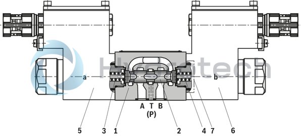
Valve with 2 spool positions (type 4WRA 6 .A...XEJ...):
The function of this valve version basically corresponds to the valve with three spool positions. The 2 spool position valves are, however, only equipped with solenoid "a" (5). Instead of the 2nd proportional solenoid, a plug screw (7) is installed.
Notice:
The tank line must not be allowed to run empty. With corresponding installation conditions, a preload valve (preload pressure approx. 2 bar) must be installed.
|
01 |
02 |
03 |
04 |
05 |
06 |
07 |
08 |
09 |
10 |
11 |
|||
|
4 |
WRA |
6 |
‒ |
2X |
/ |
G24 |
XE |
J |
/ |
* |
|
01 |
4 main ports |
4 |
|
02 |
Proportional directional valve for external control electronics |
WRA |
|
03 |
Size 6 |
6 |
|
04 |
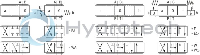
Symbols; for the possible version, see "Symbols/Circuit diagrams" |
E;E1-;W;W1-;EA;WA |
|
Nominal flow |
||
|
05 |
6 l/min |
07 |
|
10 l/min |
15 |
|
|
18 l/min |
30 |
|
|
06 |
Component series 20 ... 29 (20 ... 29: unchanged installation and connection dimensions) |
2X |
|
Supply voltage of the control electronics |
||
|
07 |
Direct voltage 24 V |
G24 |
|
Explosion protection |
||
|
08 |
“Increased safety” explosion protection; for details, please refer to the information on explosion protection |
XE |
|
Surface protection |
||
|
09 |
Seawater-resistant, galvanized |
J |
|
Seal material |
||
|
10 |
NBR seals |
M 1) |
|
FKM seals |
V |
|
|
Observe compatibility of seals with hydraulic fluid used. |
||
|
11 |
Further details in the plain text |
* |
| 1) | Suitable for mineral oils (HL, HLP) according to DIN 51524 |
general
|
Type |
4WRA | ||
|
Size |
6 | ||
|
Installation position |
any, preferably horizontal | ||
|
Ambient temperature range |
°C |
-20 … +60 | |
|
Storage temperature range |
°C |
+5 … +40 | |
|
Maximum storage time 1) |
yrs |
1 | |
|
Weight |
4WRA 6...XE |
kg |
4.4 |
|
4WRA 6...A...XE |
kg |
2.7 | |
|
Surface protection |
Galvanized | ||
| 1) | see operating instructions 29055-XE-B |
hydraulic
|
Size |
6 | ||
|
Maximum operating pressure |
bar |
315 | |
|
Maximum operating pressure |
Port P |
bar |
315 |
|
Port T |
bar |
210 | |
|
Port A |
bar |
315 | |
|
Port B |
bar |
315 | |
|
Maximum flow |
l/min |
22 | |
|
Nominal flow |
l/min |
6 10 18 |
|
|
Hydraulic fluid |
see table | ||
|
Hydraulic fluid temperature range |
NBR seals |
°C |
-20 … +80 |
|
FKM seals |
°C |
-15 … +80 | |
|
Viscosity range |
mm²/s |
20 … 380 | |
|
preferably |
mm²/s |
30 … 46 | |
|
Maximum admissible degree of contamination of the hydraulic fluid, cleanliness class according to ISO 4406 (c) 1) |
Class 17/15/12 | ||
|
Hysteresis |
% |
≤ 6 | |
|
Range of inversion |
% |
≤ 2 | |
|
Response sensitivity |
% |
≤ 1 | |
|
Maximum surface temperature |
°C |
120 | |
| 1) | The cleanliness classes specified for the components must be adhered to in hydraulic systems. Effective filtration prevents faults and simultaneously increases the life cycle of the components. For the selection of the filters, see www.boschrexroth.com/filter. |
|
Hydraulic fluid |
Classification |
Suitable sealing materials |
Standards |
Data sheet |
|
|
Mineral oils |
HL, HLP, HLPD, HVLP, HVLPD |
NBR, FKM |
DIN 51524 |
90220 |
|
|
Bio-degradable 1) |
Insoluble in water |
HETG |
FKM |
ISO 15380 |
90221 |
|
HEES |
FKM |
||||
|
Soluble in water |
HEPG |
FKM |
ISO 15380 |
||
|
Flame-resistant 1) |
Water-free |
HFDU, HFDR |
FKM |
ISO 12922 |
90222 |
|
Containing water |
HFC (Fuchs Hydrotherm 46M, Petrofer Ultra Safe 620 ) |
NBR |
ISO 12922 |
90223 |
|
|
Important information on hydraulic fluids: For further information and data on the use of other hydraulic fluids, please refer to the data sheets above or contact us. There may be limitations regarding the technical valve data (temperature, pressure range, life cycle, maintenance intervals, etc.). The ignition temperature of the hydraulic fluid used must be 50 K higher than the maximum solenoid surface temperature.Flame-resistant – containing water: Maximum operating pressure 210 bar Maximum pressure differential per control edge 175 bar Pressure pre-loading at the tank port > 20% of the pressure differential, otherwise increased cavitation erosion Life cycle as compared to operation with mineral oil HL, HLP 50 … 100% Maximum hydraulic fluid temperature 50 °CBio-degradable and flame-resistant: If these hydraulic fluids are used which are also zinc-solving, an accumulation of zinc may occur. |
|||||
| 1) | Not recommended for corrosion-protected version "J" |
electrical
|
Size |
6 | ||
|
Voltage type |
Direct current or pulse-width modulated signal with a pulse voltage ≤ 28 V and a frequency ≥ 160 Hz up to max. 500 Hz | ||
|
Type of signal |
analog | ||
|
Maximum solenoid current |
A |
1.03 | |
|
Actuated time |
% |
100 | |
|
Maximum coil temperature |
°C |
120 | |
Control electronics
|
Amplifier module for the control of explosion-proof proportional directional valves 4WRA...XE, 3DREP 6...XE and 4WRZ...XE |
VT-MSPA2-200-1X/V0/0 according to data sheet 30228-200 |
|
Module for monitoring and limiting the solenoid currents with proportional valves |
VT-MUXA2-2-1X/V0/1A according to data sheet 30290 |
|
Notice: |
|
Information on explosion protection
|
Application according to Explosion Protection Directive 2014/34/EU |
II 2G |
|
Type of protection of the valve according to EN 13463-1/ EN 13463-5 |
c T4 X |
|
Valve solenoid type of protection according to EN 60079-7 / EN 60079-18 1) |
Ex e mb IIC T4 Gb |
|
Type examination certificate solenoid |
KEMA 02ATEX2240 X |
|
“IECEx Certificate of Conformity” for solenoid |
IECEx DEK 12.0068X |
|
Special application conditions for a safe application |
– In case of bank assembly, only one solenoid of all valves may be energized at a time. ‒ In case of valves with two solenoids, only one of the solenoids may be energized at a time. ‒ Only direct current or a pulse-width modulated signal with a pulse voltage ≤ 28 V and frequency ≥ 160 Hz up to max. 500 Hz may be used. |
| 1) | Surface temperature > 50 °C, provide contact protection. |
(measured with HLP46, ϑÖl = 40 ±5 °C)
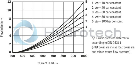
Ordering code 07: 6 l/min at a valve pressure differential of 10 bar
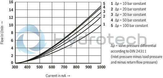
Ordering code 15: 10 l/min at a valve pressure differential of 10 bar
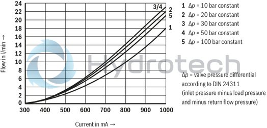
Ordering code 30: 18 l/min at a valve pressure differential of 10 bar
Performance limit rated flow 6 l/min
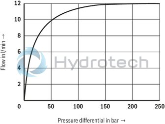
Performance limit rated flow 10 l/min
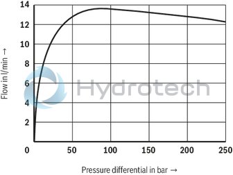
Performance limit rated flow 18 l/min
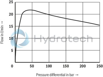
Transition function with stepped electric input signals
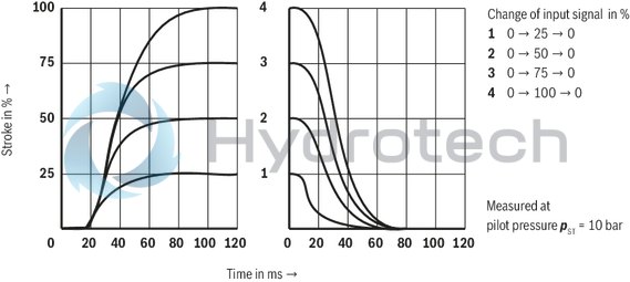
|
With control spool symbol E1- and W1-, the following applies: |
|
|
P → A: qvmax |
B → T: qv/2 |
|
P → B: qv/2 |
A → T: qvmax |
|
At symbols W, W1 and WA, there is a connection of A → T and B → T in zero position with approx. 3 % of the respective nominal cross-section. |
|
Notice:
Representation according to DIN ISO 1219-1. Hydraulic interim positions are shown by dashes.
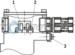
The type-examination tested valve solenoid is equipped with a terminal box and a type-tested cable gland. The connection is polarity-independent.
Notice:
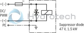
Corresponding to the rated current, a fuse according to DIN 41571 and EN / IEC 60127 has to be connected upstream of every valve solenoid (max. 3 x Irated).
The shut-off threshold of the fuse has to match the prospective short-circuit current of the supply source.
The prospective short-circuit current of the supply source may amount to a maximum of 1500 A.
This fuse may only be installed outside the potentially explosive area or must be of an explosion-proof design.
| 1) |
Recommended pre-fusecharacteristics: medium time-lag according to DIN 41571; 1.25 A |
Properties of the connection terminals and mounting elements
|
Position |
Function |
Connectable line cross-section |
|
1 |
Operating voltage connection |
Single-wire 0.75 … 2.5 mm2 |
|
Finely stranded,0.75 … 1.5 mm2 |
||
|
2 |
Connection for protective earthing conductor |
Single-wire 2.5 mm2 max. |
|
Finely stranded, 1.5 mm2 max. |
||
|
3 |
Connection for potential equalization conductor |
Single-wired, 4 … 6 mm2 |
|
Finely stranded, 4 mm2 |
Cable gland
|
Type approval |
II 2G Ex e IIC Gb |
|
Threaded connection |
M20 x 1,5 |
|
Protection class according to DIN EN 60529 |
IP66 (with correctly installed electrical connection) |
|
Line diameter |
7 … 10,5 mm |
|
Sealing |
Outer sheath sealing |
Connection line
|
Line type |
Non-armored cables and lines (outer sheath sealing) |
|
Temperature range |
–30 … > +110 °C |
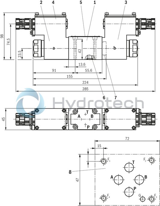
Dimensions in mm
|
|
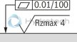
Required surface quality of the valve contact surface |
|
1 |
Valve housing |
|
2 |
Proportional solenoid "a" |
|
3 |
Proportional solenoid "b" |
|
4 |
Terminal box |
|
5 |
Name plate |
|
6 |
Identical seal rings for ports A, B, P, and T |
|
7 |
Plug screw for valves with one solenoid (2 spool positions, version "EA" or "WA") |
|
8 |
Porting pattern according to ISO 4401-03-02-0-05 (but without locating hole) |
Valve mounting screws (separate order):
For reasons of stability, exclusively the following valve mounting screws are to be used:
4 hexagon socket head cap screws ISO 4762-M5x50-10.9-flZn-240h-L
(friction coefficient 0.09 – 0.14 according to VDA 235-101)
Tightening torque MA = 7 Nm ±10%,
Material no. R913000064
Subplates (separate order) with porting pattern according to ISO 4401-03-02-0-05, see data sheet 45100.
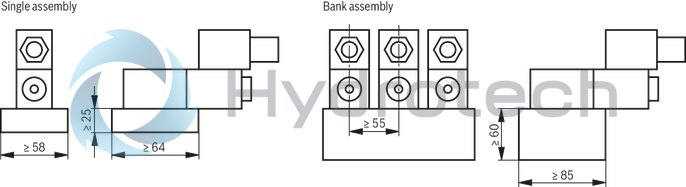
Installation conditions (dimensions in mm)
|
Single assembly |
Bank assembly |
|
|
Subplate dimensions |
Minimum dimensions: |
Minimum cross-section: |
|
Thermal conductivity of the subplate (EN-GJS-500-7) |
≥ 38 W/mK |
|
|
Minimum distance between the longitudinal valve axes |
≥ 55 mm |
|
Schematic diagram
Dimensions in mm
Notice:
In case of bank assembly, only one solenoid of all valves may be energized at a time.