

BOSCH REXROTH
R901088382
$5,888.74 USD
- BOSCH REXROTH
- Material:R901088382
- Model:SFE100Z0-1X/M
Quantity in stock: 0
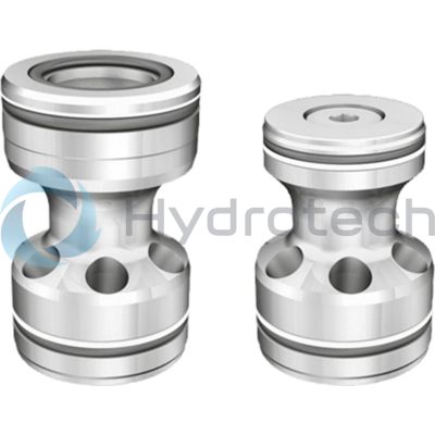
The Bosch Rexroth SFE100Z0-1X/M (R901088382) is a high-performance industrial hydraulic valve designed for reliable blocking of oil flow at selected ports. This seat valve, pilot-operated and belonging to component series X, is characterized by its spool symbol A B and its capability to withstand a maximum pressure in demanding applications. It features a number of ports suitable for various configurations and employs hydraulic actuation for precise control. The SFE100Z0-1X/M valve has a size that fits standard requirements and ensures optimal flow within hydraulic systems. Its connection type is a cartridge valve, which allows for streamlined integration into existing setups. The connection diagram adheres to ISO standards, ensuring compatibility and ease of installation. With multiple switching positions, this valve offers versatility in operation. Weighing in at an efficient mass, the SFE100Z0-1X/M is designed with NBR seals that are compatible with hydraulic fluids such as HL, HLP, HLPD, HVLP, HVLPD, and HFC. This range of fluid compatibility highlights the valve's adaptability across different system requirements. Additionally, the SEF type Z valve can be optionally fitted with a cover type LFF for added functionality and protection. Whether it's used in block or cylinder installations, this pilot-operated prefill valve check valve ensures reliable performance in controlling fluid flow within industrial hydraulic systems. With its robust design and precise operation capabilities, the Bosch Rexroth SFE100Z0-1X/M (R901088382) stands out as an essential component for advanced hydraulic applications requiring dependable flow control.
Size 100, A → B, hydraulically actuated
Industrial hydraulic valve in a high performance range. Reliable blocking of the oil flow at selected ports.
Unpacked Weight: 22.360 kg
Type "SEF . Z" (with optional cover type "LFF")
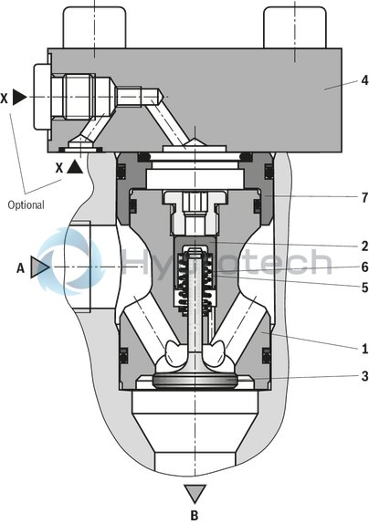
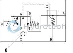
| Seat valve |
| Pilot-operated |
| Component series 1X |
| Size 25 … 100 |
| Maximum operating pressure 350 bar |
| Maximum flow 2000 l/min |
| Data Sheet | Download Data Sheet |
| 3D CAD | Download 3D CAD |
| Manual | Download Manual |
| Manual | Download Manual |
| Manual | Download Manual |
| Manual | Download Manual |
| Manual | Download Manual |
| Spool symbol | A → B |
| Max. pressure | 350 |
| Productgroup ID | 9,10,11,12,13,14 |
| Number of ports | 2 |
| Type of actuation | with hydraulic actuation |
| Size | 100 |
| Max. flow | 1400 |
| Type of connection | Cartridge valve |
| Connection diagram | ISO 7368 |
| Number of switching positions | 2 |
| Weight | 22.360 |
| Seals | NBR |
| Hydraulic fluid | HL,HLP,HLPD,HVLP,HVLPD,HFC |
|
01 |
02 |
03 |
04 |
05 |
06 |
07 |
||
|
SFE |
0 |
– |
1X |
/ |
M |
* |
|
01 |
Prefill valves |
SFE |
|
02 |
Size 25 |
25 |
|
Size 32 |
32 |
|
|
Size 40 |
40 |
|
|
Size 50 |
50 |
|
|
Size 63 |
63 |
|
|
Size 80 |
80 |
|
|
Size 100 |
100 |
|
|
03 |
Block installation |
P |
|
Cylinder installation 1) |
Z |
|
|
04 |
without pre-decompression |
0 |
|
05 |
Component series 10 ... 19 (10 ... 19: unchanged installation and connection dimensions) - Size 10 |
1X |
|
Seal material |
||
|
06 |
NBR seals (other seals on request) |
M |
|
Observe compatibility of seals with hydraulic fluid used. |
||
|
07 |
Further details in the plain text |
* |
1) Control cover type “LFF” incl. matching mounting kit (separate order, see page 8):
With NG25 and 32, alternative control covers type "LFA.D-7X/....F…" (see RE 21010) may be used.
general
|
Size |
25 | 32 | 40 | 50 | 63 | 80 | 100 | |
|
Weight |
kg |
0.53 | 1.05 | 1.94 | 3.2 | 6.48 | 10.3 | 22.15 |
|
Installation position |
any | |||||||
|
Ambient temperature range 1) |
°C |
-30 … +80 | ||||||
| 1) | NBR seals |
hydraulic
|
Size |
25 | 32 | 40 | 50 | 63 | 80 | 100 | ||
|
Maximum operating pressure |
Port P |
bar |
350 | ||||||
|
Anschluss A |
bar |
16 | |||||||
|
Port B |
bar |
350 | |||||||
|
Anschluss X |
bar |
150 | |||||||
|
Cracking pressure 1) |
bar |
≈ 0.12 | |||||||
|
Maximum flow 2) |
Case of application 1 |
l/min |
100 | 170 | 240 | 360 | 580 | 810 | 1210 |
|
Case of application 2 |
l/min |
90 | 140 | 200 | 320 | 510 | 710 | 1070 | |
|
Case of application 3 |
l/min |
60 | 100 | 140 | 220 | 350 | 480 | 730 | |
|
Case of application 4 |
l/min |
50 | 70 | 100 | 160 | 260 | 360 | 540 | |
|
Druckflüssigkeit |
Mineral oil (HL, HLP) to DIN 51524;fast bio-degradable hydraulic fluids according to VDMA 24568; HETG (rape seed oil); other hydraulic fluids on enquiry | ||||||||
|
Hydraulic fluid temperature range |
°C |
-30 … +80 | |||||||
|
Viscosity range |
mm²/s |
10 … 800 | |||||||
|
Maximum admissible degree of contamination of the hydraulic fluid 3) |
Class 20/18/15 according to ISO 4406 (c) | ||||||||
| 1) | Pressure differential at the main poppet for overcoming the spring force |
| 2) | Pulling function (A to B) |
| 3) | The cleanliness classes specified for the components must be adhered to in hydraulic systems. Effective filtration prevents faults and simultaneously increases the life cycle of the components. For the selection of the filters, see www.boschrexroth.com/filter. |
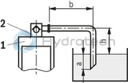
Flow ‒ case of application 1 (A to B)
Flow ‒ case of application 2 (A to B)
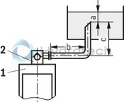
Size of the filling tank at least 1.5 x cylinder content
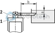
Flow ‒ case of application 3 (A to B)
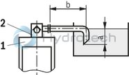
Flow ‒ case of application 4 (A to B)
Attention!
Faulty dimensioning of prefill valves and connection lines may lead to cavitation effects. The consequences affect the reliability and durability of products!
Attention!
An underdimensioned prefill valve and/or an underdimensioned line leads to gas leaks from the hydraulic fluid with corresponding consequences and often to long-term damage at the cylinder seals.
Notice!
For limit areas, please contact us. It is often sufficient, to select a pipeline which is one size larger.
|
1 |
Cylinders |
|
2 |
Prefill valve |
|
a |
at least 300 mm with extended cylinder |
|
b |
up to 1000 mm with the specified maximum flows |
|
c |
≤ 500 mm |
|
h |
300 mm ≤ h ≤ 500 mm |
For applications outside these parameters, please consult us!
(measured with HLP46, ϑOil {ν = [si]40 mm2/s[/si][imp]40 cSt[/imp]) = [si]40 ±5 °C[/si][imp]104 ±41 °F[/imp])
NG25
Pressure differential Δp between ports A and B dependent on the flow qV in suction direction.
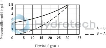
NG25
Pressure differential Δp between ports A and B dependent on the flow qV in suction direction.
Size 32
Pressure differential Δp between ports A and B dependent on the flow qV in suction direction.
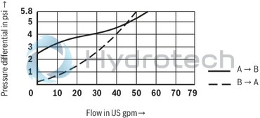
Size 32
Pressure differential Δp between ports A and B dependent on the flow qV in suction direction.
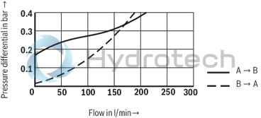
NG40
Pressure differential Δp between ports A and B dependent on the flow qV in suction direction.
NG40
Pressure differential Δp between ports A and B dependent on the flow qV in suction direction.
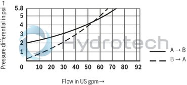
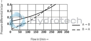
NG50
Pressure differential Δp between ports A and B dependent on the flow qV in suction direction.
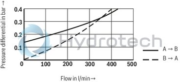
NG50
Pressure differential Δp between ports A and B dependent on the flow qV in suction direction.
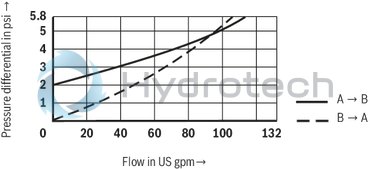
NG63
Pressure differential Δp between ports A and B dependent on the flow qV in suction direction.
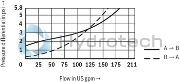
NG63
Pressure differential Δp between ports A and B dependent on the flow qV in suction direction.
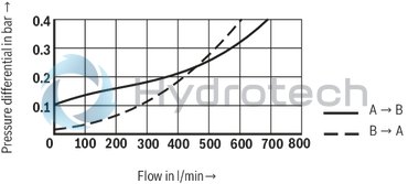
NG80
Pressure differential Δp between ports A and B dependent on the flow qV in suction direction.
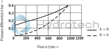
NG80
Pressure differential Δp between ports A and B dependent on the flow qV in suction direction.
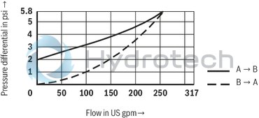
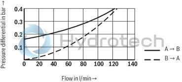
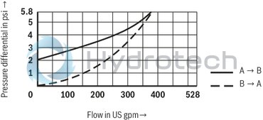
Size 100
Pressure differential Δp between ports A and B dependent on the flow qV in suction direction.
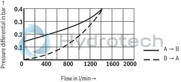
Size 100
Pressure differential Δp between ports A and B dependent on the flow qV in suction direction.
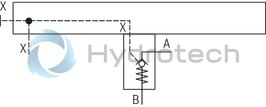
Prefill valve type SFE

Prefill valve type SFE with control cover type LFF
Installation bore for block installation type SFE . P
Dimensions in mm
| 1) | Fit |
Installation bore for block installation type SFE . P
Dimensions in mm
| 1) | Fit |
|
1 |
Port A can be positioned anywhere around the central axis. However, it must be observed that the control bores and the mounting bores are not damaged! |
|
2 |
Block |
|
3 |
Cylinders |
|
NG |
ØD1H7 / ØD8 |
ØD2H7 / ØD7 |
ØD3 |
ØD4 |
ØD5 |
ØD6 |
H1 |
P1 1) |
P2 1) |
T1 |
T2 |
T3 |
T4 |
T5 |
||
|
mm |
mm |
mm |
mm |
mm |
mm |
mm |
mm |
mm |
mm |
mm |
mm |
mm |
mm |
mm |
mm |
|
| 25 | 43 | 37 | 25 | - 5 | 36 | 25 | 7 | 7 | 30 | 13 | 70 | + 0.1 | 56 | 43.5 | 2.5 | 2.5 |
| 32 | 58 | 50 | 31 | - 5 | 46 | 32 | 7 | 9 | 30 | 13 | 78 | + 0.1 | 63 | 47 | 2.5 | 2.5 |
| 40 | 75 | 55 | 40 | - 5 | 58 | 40 | 7 | 11 | 26 | 16 | 81 | + 0.1 | 63 | 43 | 3 | 3 |
| 50 | 90 | 68 | 50 | - 5 | 71 | 50 | 7 | 14 | 31 | 20 | 100 | + 0.1 | 78 | 53 | 4 | 3 |
| 63 | 120 | 90 | 63 | - 5 | 90 | 60 | 7 | 16 | 32 | 23 | 114 | + 0.1 | 89 | 59 | 4 | 4 |
| 80 | 145 | 110 | 78.5 | - 5 | 107 | 76 | 7 | 18 | 36 | 23 | 134 | + 0.1 | 109 | 71 | 5 | 5 |
| 100 | 180 | 135 | 95 | - 5 | 132 | 93 | 7 | 30 | 60 | 30 | 180 | + 0.1 | 148 | 101 | 8 | 8 |
| 1) | Fit |
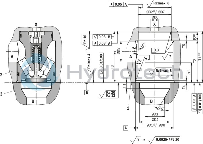
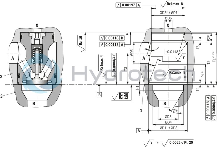
Installation bore for cylinder installation type SFE . Z
Dimensions in mm
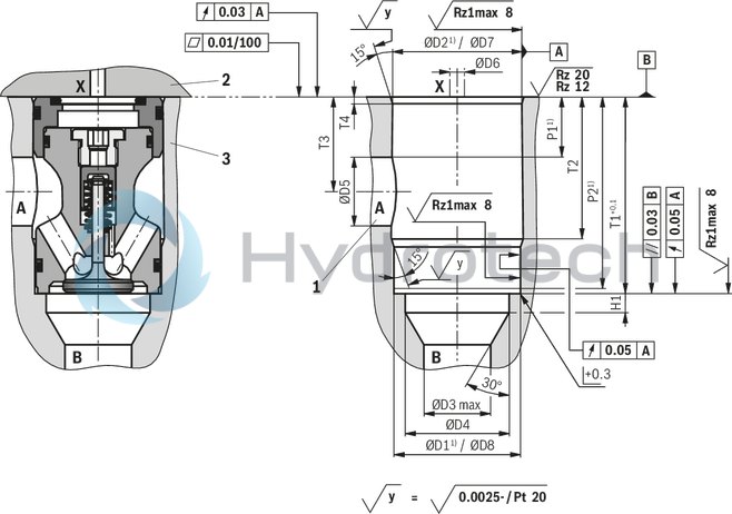
| 1) | Fit |
Installation bore for cylinder installation type SFE . Z
Dimensions in mm
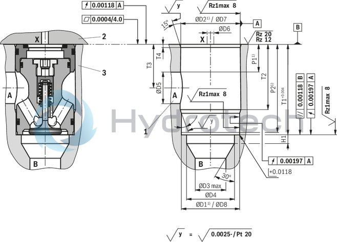
| 1) | Fit |
|
1 |
Port A can be positioned anywhere around the central axis. However, it must be observed that the control bores and the mounting bores are not damaged! |
|
2 |
Cover |
|
3 |
Cylinders |
|
NG |
ØD1H7 / ØD8 |
ØD2H7 / ØD7 |
ØD3 |
ØD4 |
ØD5 |
ØD6 |
H1 |
P1 1) |
P2 1) |
T1 |
T2 |
T3 |
T4 |
||
|
mm |
mm |
mm |
mm |
mm |
mm |
mm |
mm |
mm |
mm |
mm |
mm |
mm |
mm |
mm |
|
| 25 | 43 | 45 | 25 | - 5 | 36 | 25 | 7 | 7 | 27 | 83 | 85 | + 0.1 | 60 | 41 | 2.5 |
| 32 | 58 | 60 | 31 | - 5 | 46 | 32 | 7 | 9 | 28 | 89.5 | 91.5 | + 0.1 | 66 | 44 | 2.5 |
| 40 | 75 | 78 | 40 | - 5 | 58 | 40 | 7 | 11 | 30 | 91 | 93 | + 0.1 | 71 | 50 | 3 |
| 50 | 90 | 90 | 50 | - 5 | 71 | 50 | 7 | 14 | 34 | 110 | 112 | + 0.1 | 85 | 59 | 4 |
| 63 | 120 | 123 | 63 | - 5 | 90 | 60 | 7 | 16 | 40 | 128 | 130 | + 0.1 | 101 | 71 | 4 |
| 80 | 145 | 150 | 78.5 | - 5 | 107 | 76 | 7 | 18 | 40 | 148 | 150 | + 0.1 | 117 | 79 | 5 |
| 100 | 180 | 185 | 95 | - 5 | 132 | 100 | 7 | 30 | 50 | 188 | 200 | + 0.1 | 152 | 101 | 8 |
| 1) | Fit |
Installation bore and connection dimensions according to ISO 7368
Dimensions in mm
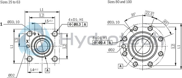
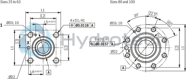
Installation bore and connection dimensions according to ISO 7368
Dimensions in mm
Tolerances:
General tolerances ISO 2768-mK Tolerancing principle ISO 8015Dimensions
|
NG |
ØD2 |
ØD3H13 |
L1 |
L2 |
L3 |
L4 |
L5 |
H1 |
|
|
mm |
mm |
mm |
mm |
mm |
mm |
mm |
mm |
mm |
|
| 25 | 6 | - 0.5 | 5 | 85 | 58 | 29 | 33 | 16 | 25 |
| 32 | 8 | - 0.5 | 5 | 102 | 70 | 35 | 41 | 17 | 35 |
| 40 | 10 | - 0.5 | 5 | 125 | 85 | 42.5 | 50 | 23 | 45 |
| 50 | 10 | - 0.5 | 8 | 140 | 100 | 50 | 58 | 30 | 45 |
| 63 | 12 | - 0.5 | 8 | 180 | 125 | 62.5 | 75 | 38 | 65 |
| 80 | 16 | - 0.5 | 10 | 250 | 200 | - | - | - | 50 |
| 100 | 20 | - 0.5 | 10 | 300 | 245 | - | - | - | 63 |
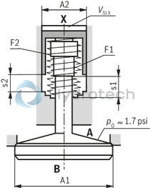
Poppet geometry and determination of the minimum pilot pressure
Dimensions in mm
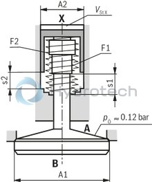
Poppet geometry and determination of the minimum pilot pressure
Dimensions in mm
|
A1 |
Effective area of the main poppet |
|
A2 |
Effective area of the control spool |
|
s1 |
Stroke of the main poppet |
|
s2 |
Stroke of the control spool |
|
F1 |
Spring force of the valve spring |
|
F2 |
Spring force of the compression spring of the control spool |
|
Vst X |
Pilot volume for opening the valve |
|
pÖ |
Cracking pressure (pressure differential at the main poppet for overcoming the spring force F1) |
|
pSt |
Pilot pressure at port X |
|
pB |
System pressure at port B |

|
|
NG |
A1 |
A2 |
s1 |
s2 |
F1 |
F2 |
VstX |
Unchecking ratio |
|
cm² |
cm² |
mm |
mm |
N |
N |
cm³ |
||
| 25 | 5.31 | 1.33 | 6.2 | 5 | 6 … 14 | 38 … 70 | 0.66 | 4 |
| 32 | 8.04 | 2.01 | 8.5 | 6.5 | 9 … 22 | 58 … 109 | 1.3 | 4 |
| 40 | 13.52 | 3.14 | 10 | 7 | 14 … 29 | 93 … 162 | 2.2 | 4.3 |
| 50 | 21.24 | 4.71 | 12.5 | 9 | 23 … 49 | 149 … 261 | 4.2 | 4.5 |
| 63 | 32.67 | 7.07 | 14.5 | 11 | 35 … 63 | 206 … 348 | 7.8 | 4.6 |
| 80 | 49.02 | 10.18 | 17 | 13 | 57 … 127 | 310 … 579 | 13.2 | 4.8 |
| 100 | 73.13 | 15.9 | 22 | 16 | 81 … 193 | 476 … 952 | 25.5 | 4.6 |
Example: Type SFE32...
pB = 30 bar [435 psi];
pSt = 4.0 x 30 bar [435 psi] = 129 bar [1740 psi]