

BOSCH REXROTH
R901086081
$531.00 USD
- BOSCH REXROTH
- Material:R901086081
- Model:Z1S6C05-4X/V
Quantity in stock: 0
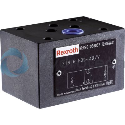
The Bosch Rexroth Z1S6C05-4X/V (R901086081) is a high-performance industrial hydraulic valve designed for reliable blocking of oil flow at selected ports. This seat valve is directly actuated with a cracking pressure of . bar and features a spool symbol A A. With its maximum pressure capability, the Z1S6C05-4X/V ensures efficient operation in demanding applications. Its mechanical actuation allows for precise control, and the valve is equipped to handle a max flow rate as specified. This model boasts an electrical connection that adheres to the standards set by NFPA T.. R D SizeCETOP D and ISO, ensuring compatibility with various systems. The Z1S6C05-4X/V has multiple ports and switching positions, making it versatile for different circuit configurations. The weight of the valve is optimized for its size and functionality. The hydraulic fluid compatibility range for this valve includes HL, HLP, HLPD, HVLP, HVLPD, HETG, HEES, HEPG, HFDU, and HFDR types. Its seals are made from FKM material which provides excellent resistance to high temperatures and chemical wear. Designed as a sandwich plate valve suitable for vertical stackings, the Z1S6C05-4X/V can function both as an angle valve or straight-through valve. It offers various one-channel and two-channel blocking functions with perfect leak tightness due to its high-performance plastic poppet design. The corrosion-protected construction ensures longevity even in harsh environments. Additionally, this Bosch Rexroth hydraulic valve can be easily adjusted to special hydraulic fluids by exchanging the external seal rings. Optional measuring ports are available along with the possibility of using it as a throttle check valve upon request. Its porting pattern conforms to ISO standards which simplifies integration into existing systems. The maximum operating pressure supported by this component series X is bar while accommodating a maximum flow of l/min as per the order specifications provided.
Size 6, A1 → A2, mechanically actuated
Industrial hydraulic valve in a high performance range. Reliable blocking of the oil flow at selected ports.
Unpacked Weight: 0.78 kg
The valve type Z1S is a direct operated check valve in sandwich plate design.
It is used for the leakage-free blocking in one direction and allows for free flow in the opposite direction.
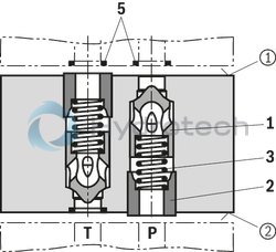
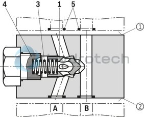
The stroke of the poppet (1) is limited by the plastic socket (2). The installed spring (3) supports the closing movement. When no fluid flows through the valve, the spring (3) keeps the poppet (1) in closed position.
In contrast to the straight-through valve (section 1), the angle valve (section 2) links or closes off up to three internal channels. Stop and sealing function are taken over by the plug screw (4).
Notice:
For all installation positions in which the blue plastic socket (2) is mounted at the plate side ➁, no additional seal ring may be used at this position!
At the component side ➀, the seal ring (5) (as usual) seals the assembly installed downstream.
The installed plastic socket (2) has a sealing function and may not be removed or damaged.
Section 1: Type Z12 6 F (straight-through valve)
Section 2: Type Z1S 6 B-A (angle valve)
| Seat valve |
| Direct actuated |
| Cracking pressure 0.5 bar |
| Maximum flow 40 l/min |
| Size 6 |
| Maximum operating pressure 350 bar |
| Component series 4X |
| Data Sheet | Download Data Sheet |
| 3D CAD | Download 3D CAD |
| Manual | Download Manual |
| Manual | Download Manual |
| Manual | Download Manual |
| Manual | Download Manual |
| Manual | Download Manual |
| Spool symbol | A1 → A2 |
| Max. pressure | 350 |
| Electrical connection description | 0 |
| Productgroup ID | 9,10,11,12,13,14 |
| Number of ports | 4 |
| Type of actuation | with mechanical actuation |
| Size | 6 |
| Max. flow | 40 |
| Type of connection | Interim assembly |
| Connection diagram NFPA | NFPA T3.5.1 R2-2002 D03 |
| Size_CETOP | D03 |
| Connection diagram | ISO 4401-03-02-0-05 |
| Number of switching positions | 2 |
| Weight | 0.78 |
| Seals | FKM |
| Hydraulic fluid | HL,HLP,HLPD,HVLP,HVLPD,HETG,HEES,HEPG,HFDU,HFDR |
|
01 |
02 |
03 |
04 |
05 |
06 |
07 |
08 |
09 |
10 |
|||
|
Z1S |
6 |
– |
4X |
/ |
V |
/ |
* |
|
01 |
Check valve, Sandwich plate design |
Z1S |
|
02 |
Size 6 |
6 |
|
Direction of flow |
||
|
03 |
Straight-through valve (in the channel) |
|
|
A (A2 → A1) |
A |
|
|
B (B2 → B1) |
B |
|
|
A (A1 → A2) |
C |
|
|
B (B1 → B2) |
D |
|
|
A and B (A1 → A2) and (B1 → B2) |
E |
|
|
P and T (P2 → P1) and (T1 → T2) |
F |
|
|
P (P2 → P1) |
P |
|
|
T (T1 → T2) |
T |
|
|
Angle valve |
||
|
B → A |
B-A |
|
|
T → P |
T-P |
|
|
AB → P |
AB-P |
|
|
Symbols; for the possible version, see "Symbols/Circuit diagrams" |
||
|
Cracking pressure |
||
|
04 |
0,5 bar |
05 |
|
1,5 bar |
15 |
|
|
3,0 bar |
30 |
|
|
5,0 bar |
50 |
|
|
05 |
Component series 40 … 49 (40 … 49: unchanged installation and mounting dimensions) |
4X |
|
Seal material |
||
|
06 |
FKM seals |
V |
|
Observe compatibility of seals with hydraulic fluid used. (Other seals upon request) |
||
|
Corrosion resistance (outside; thick film passivated according to DIN 50979 Fe//Zn8//Cn//T0) |
||
|
07 |
None (valve housing primed) |
no code |
|
Improved corrosion protection (240 h salt spray test according to EN ISO 9227) |
J3 |
|
|
08 |
Without locating hole |
no code |
|
With locating hole |
/601) |
|
|
With locating hole and locking pin ISO 8752-3x8-St |
/62 |
|
|
Special version |
||
|
09 |
Standard version |
no code |
|
Measuring port in P (G1/4; on channel B side) |
SO68 |
|
|
Measuring port in P (G1/4; on channel A side) |
SO118 |
|
|
Measuring ports A and B (G1/4) |
SO90 |
|
|
Measuring port T (G1/4 |
SO2 |
|
|
Direction of flow P1 → P2 (opposite to version "P") |
SO104 |
|
|
Symbols (examples) see "Symbols/Circuit diagrams" |
||
|
10 |
Further details in the plain text |
* |
| 1) | Locking pin ISO 8752-3x8-St, material no. R900005694 (separate order) |
general
|
Size |
6 | |
|
Weight |
kg |
0.8 |
|
Installation position |
any | |
|
Ambient temperature range |
°C |
-20 … +80 |
For applications outside these parameters, please consult us!
hydraulic
|
Size |
6 | |
|
Maximum operating pressure |
bar |
350 |
|
Cracking pressure |
bar |
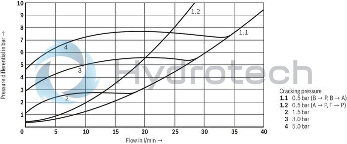
0.5 / 1.5 / 3 / 5 |
|
Maximum flow |
l/min |
40 |
|
Hydraulic fluid |
see table | |
|
Hydraulic fluid temperature range |
°C |
-20 … +80 |
|
Viscosity range |
mm²/s |
2.8 … 500 |
|
Maximum admissible degree of contamination of the hydraulic fluid, cleanliness class according to ISO 4406 (c) 1) |
Class 20/18/15 | |
| 1) | The cleanliness classes specified for the components must be adhered to in hydraulic systems. Effective filtration prevents faults and simultaneously increases the life cycle of the components. For the selection of the filters, see www.boschrexroth.com/filter. |
|
Hydraulic fluid |
Classification |
Suitable sealing materials |
Standards |
Data sheet |
|
|
Mineral oils |
HL, HLP, HLPD, HVLP, HVLPD |
NBR, FKM |
DIN 51524 |
90220 |
|
|
Bio-degradable |
Insoluble in water |
HETG |
NBR, FKM |
ISO 15380 |
90221 |
|
HEES |
FKM |
||||
|
Soluble in water |
HEPG |
FKM |
ISO 15380 |
||
|
Flame-resistant |
Water-free |
HFDU |
FKM |
ISO 12922 |
90222 |
|
HFDR |
FKM |
||||
|
Containing water |
HFC (Fuchs Hydrotherm 46M, Petrofer Ultra Safe 620) |
NBR |
ISO 12922 |
90223 |
|
|
Important information on hydraulic fluids: For more information and data on the use of other hydraulicfluids, please refer to the data sheets above or contact us. There may be limitations regarding the technical valve data (temperature, pressure range, life cycle, maintenance intervals, etc.). The ignition temperature of the hydraulic fluid used must be 50 K higher than the maximum surface temperature. Flame-resistant - containing water: Maximum pressure differential per control edge 50 bar Pressure pre-loading at the tank port > 20 % of the pressure differential, otherwise increased cavitation Life cycle as compared to operation with mineral oil HL, HLP 50 … 100%. Bio-degradable and flame-resistant – containing water: If this hydraulic fluid is used, small amounts of dissolved zinc may get into the hydraulic system. |
|||||
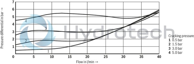
(measured with HLP46, ϑOil = 40 ±5 °C)
Straight-through valve
∆p-qV-characteristic curves (A2 → A1)
Angle valve
Straight-through valve (➀ = component side, ➁ = plate side)
Version "A"

Version "D"

Version "P"
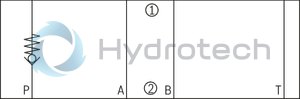
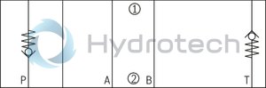
Version "B"

Version "E"

Version "T"

Version "C"

Version "F"
Angle valve (➀ = component side, ➁ = plate side)
Version "AB-P"
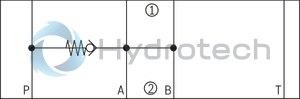
Version "T-P"
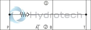
Version "B-A"

Examples of special versions (➀ = component side, ➁ = plate side)
Version "SO68"
(check valve in channel P, measuring port P Out G1/4)
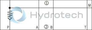
Version "SO118"
(check valve in channel P, measuring port P Out G1/4)
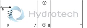
Version "SO90"
(check valve in channel P, measuring port A and B G1/4)
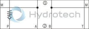
Version "SO2"
(check valve in channel P, measuring port T G1/4)
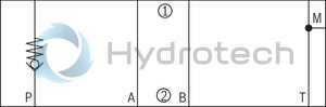
Version "SO104"
(check valve in channel P, direction of flow P1 → P2)
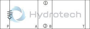
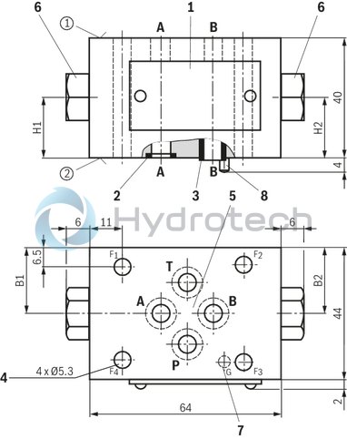
Straight-through valve
Dimensions in mm
|
|
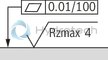
Required surface quality of the valve contact surface |
|
Type |
B1 |
B2 |
H1 |
H2 |
|
mm |
mm |
mm |
mm |
|
| Z1S 6 C...SO68 | 22 | - | 13.5 | - |
| Z1S 6 P...SO68 | - | 26.5 | - | 13 |
| Z1S 6 P...SO118 | 26.5 | - | 13 | - |
| Z1S 6 P...SO90 | 22 | 22 | 20 | 20 |
| Z1S 6 P...SO2 | - | 17.5 | - | 20 |
|
① |
component side |
|
② |
plate side |
|
1 |
Name plate |
|
2 |
Identical seal rings for ports A, B, P, T (plate side) |
|
3 |
Plastic socket, blue (plate side) |
|
4 |
Valve mounting bores |
|
5 |
Porting pattern according to ISO 4401-03-02-0-05 |
|
6 |
Plug screw for measuring port, tightening torque MA = 30 Nm + 10 % |
|
7 |
Locking pin ISO 8752-3x8-St (only version "60" and "62") |
|
8 |
Bore for locking pin (only version "60" and "62") |
Valve mounting screws (separate order)
|
Size |
Quantity |
Hexagon socket head cap screws |
Material number |
|
6 |
4 |
ISO 4762 - M5 10.9 |
- |
Notice:
Length and tightening torque of the valve mounting screws must be calculated according to the components mounted under and over the sandwich plate valve.
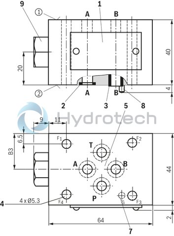
Angle valve
Dimensions in mm
|
|
|
Required surface quality of the valve contact surface |
|
Type |
B3 |
|
mm |
|
| Z1S 6 AB-P | 24.5 |
| Z1S 6 T-P | 24.5 |
| Z1S 6 B-A | 22 |
|
1 |
Name plate |
|
2 |
Identical seal rings for ports A, B, P, T (plate side) |
|
3 |
Plastic socket, blue (plate side) |
|
4 |
Valve mounting bores |
|
5 |
Porting pattern according to ISO 4401-03-02-0-05 |
|
7 |
Locking pin ISO 8752-3x8-St (only version "60" and "62") |
|
8 |
Bore for locking pin (only version "60" and "62") |
|
9 |
Plug screw, tightening torque MA = 55 Nm + 10 % |
|
① |
component side |
|
② |
plate side |
Valve mounting screws (separate order)
|
Size |
Quantity |
Hexagon socket head cap screws |
Material number |
|
6 |
4 |
ISO 4762 - M5 10.9 |
- |
Notice:
Length and tightening torque of the valve mounting screws must be calculated according to the components mounted under and over the sandwich plate valve.
Check valve installation set: Disassembly and assembly
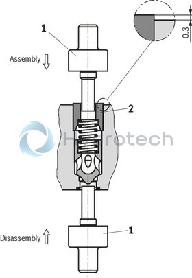
Disassembly/assembly without causing damage is achieved by using the special multi-purpose tool (1) (separate order, material no. R901182853).
Disassembly:
Push out the check valve installation set.
Assembly:
Insert the check valve installation set and push in the plastic socket (2).
With correct assembly using the special multi-purpose tool (1), the protrusion of the plastic socket (2) is approx. 0.3 mm.
Notice:
Once removed, plastic sockets may no not be used again.
Notes
Valve housing (steel) and plastic spool with plastic socket can be disassembled into individual components for proper disposal. The check valve installation set is available separately (plastic socket, plastic spool, spring): E-Mail: spare.parts@boschrexroth.de The plastic socket has a sealing function and may therefore not be damaged. For installation and disassembly of the check valve installation set, a special multi-purpose tool is required, see "Mounting".Troubleshooting
|
External leakage at the flow passages |
Seal ring faulty. |
Replace seal rings (seal kit). |
|
Lip of the plastic socket is damaged. |
Replace check valve installation set. 1) |
|
|
Mounting screws tightened unevenly. |
Loosen screws and tighten them again crosswise using the recommended tightening torque. |
|
|
Internal leakage at the check valve installation set |
Foreign particle on poppet surface. |
Check poppet surface from the outside for foreign particles and remove them. |
|
Poppet does not move freely. |
Check free movement of the poppet from the outside using an appropriate mandrel. Caution - do not push the plastic socket out of the housing! |
|
|
Leakage caused by downstream assembly. |
Check if the check valve installation set is the reason for the leakage. |
|
|
Hydraulic fluid quality does not correspond to the specification. |
Check hydraulic fluid quality and adjust it to the specifications, if required. |
|
|
Dependent on the included hydraulic fluid volume and its temperature variations, there may be pressure changes which are not due to leakage. |
||
|
If the measures described above are not successful. |
Completely replace the check valve installation set. 1) |
|
|
External leakage at measuring points |
Seal faulty. |
Replace profile seal. |
|
Plug screw or fitting not tightened correctly. |
Tighten plug screw or fitting using the specified tightening torque. |
|
| 1) | Use the special multi-purpose tool to avoid damaging the plastic socket, see "Mounting". |