


BOSCH REXROTH
R901080965
$1,271.09 USD
- BOSCH REXROTH
- Material:R901080965
- Model:VT-MRPA1-150-1X/V0/0
Quantity in stock: 0
The Bosch Rexroth VT-MRPA1-150-1X/V0/0 (R901080965) is an advanced amplifier module designed for use with proportional valves in hydraulic systems. This module is engineered to be easily mounted on top hat rails in accordance with EN standards and connects electrically through screw terminals, operating on a direct voltage of V. It features a built-in power supply unit equipped with a making current limiter that supplies all necessary internal voltages while preventing high current peaks during activation. With command value presetting, the VT-MRPA1-150-1X/V0/0 calculates the internal command value signal by combining the external command value signal from the differential input and adjustments made via the zero point potentiometer. This function ensures that solenoid current and corresponding valve pressure increase proportionally to positive command values. The enable function of this amplifier module activates the current output stages and conveys the internal command value signal to the ramp generator. This function includes an LED indicator and ensures that any valve control is not abrupt but gradual, following a set ramp time. The ramp generator within the module controls the incline of the control output without altering ramp time, which can be set and measured through specific sockets and calculations provided by Bosch Rexroth. Additionally, an amplitude attenuator allows for hydraulic requirements to be met by adjusting maximum values, while an amplitude limiter confines internal command values within preset bounds. This module also incorporates an oscillator for generating control signals for inductive position transducers, a demodulator for actual value signal processing from transducer signals, and a controller optimized to reduce valve hysteresis. The robust current output stage delivers pulsed solenoid current up to a limited amount and features short-circuit protection as well as deactivation under fault conditions or missing enable signals. For fault recognition, this product monitors position transducer cables for breakages or short circuits on the primary side and detects overcurrents at its output stage. Its modular design is compatible with FREX valves within component series X and includes additional features such as differential input voltage, adjustable zero point/sensitivity, enable input, cable break detection for actual value cables, reverse polarity protection for operating voltage, along with LED displays indicating operation readiness and enable status.
General information
The amplifier modules are snapped onto top hat rails according to EN 60715. The electrical connection is established via screw terminals. The modules are operated at 24 V direct voltage.
Power supply unit [1]
The amplifier modules have a power supply unit with making current limiter. This unit supplies all internally required positive and negative supply voltages. The making current limiter prevents high making current peaks.
Command value presetting
The internal command value signal is
calculated from the total [3] of the external command value signal available at the differential input [2] and the zero point offset (zero point potentiometer "Zw").
A positive command value results in a current increase in the solenoid and thus a pressure increase in the valve.
Enable function [11]
The enable function enables the current output stages and forwards the internal command value signal to the ramp generator. The enable signal is indicated by an LED on the front plate. If enable is connected, the internal command value is changed (with any kind of command value presetting) by the set ramp time. Thus, a controlled valve does not open abruptly.
Ramp generator [4]
The ramp generator limits the incline of the control output. The amplitude attenuator does not extend or shorten the ramp time.
Information on ramp time settings and measurement:
|
Value at measuring socket |
U/V |
5 |
3 |
2 |
1 |
0.5 |
0.3 |
0.2 |
0.1 |
0.05 |
0.03 |
0.02 |
|
Current ramp time (±20 %) |
t/ms |
20 |
33 |
50 |
100 |
200 |
333 |
500 |
1000 |
2000 |
3333 |
5000 |
Formula for calculation of the ramp times:
t in ms, U in volt at the measuring socket
Amplitude attenuator [5]
By means of the amplitude attenuator "Gw", the maximum value can be adjusted to the hydraulic requirements in a range between 0 and 100 %.
Amplitude limiter [6]
The internal command value is limited to 0 % and 110 %.
Oscillator [9]
The oscillator creates the control signal for the inductive position transducer.
Demodulator [10]
The demodulator supplies the actual value signal of the control spool position from the position transducer signal.
+100 % ≙ +10 V at measuring socket "x"
Controller for the control spool position [7]
The position controller is intended to minimize the valve hysteresis and is optimized in a valve-specific manner.
Current output stage [8]
The current output stage creates the clocked solenoid current for the proportional valve. The solenoid current is limited to approx. 1.85 A. The output stage output is short-circuit-proof. The output stage is de-energized in case of an internal fault signal or if the enable signal is missing.
Fault recognition [14]
The position transducer cable is monitored for cable break and short-circuits on the primary side as well as for over-currents at the output stage.
[ ] = Assignment to the block diagram
|
01 |
Valve amplifier for proportional flow control valves with electrical position feedback, analog, modular design |
VT-MRPA1 |
|
02 |
For valves: 2FRE 6 |
150 |
|
03 |
Component series 10 ... 19 (10 ... 19: unchanged installation and connection dimensions) |
1X |
|
04 |
Version: standard |
V0 |
|
05 |
Option: standard |
0 |
|
06 |
Further details in the plain text |
* |
|
01 |
02 |
03 |
04 |
05 |
06 |
|||||
|
VT-MRPA1 |
‒ |
150 |
‒ |
1X |
/ |
V0 |
/ |
0 |
/ |
* |
General
|
Component series |
1X | |
|
Type of electronics |
Analog | |
|
Design |
Modul |
Voltage supply
|
Operating voltage |
nominal |
U |
V |
24 |
|
Lower limit value |
UB(t)min |
V |
18 | |
|
Upper limit value |
UB(t)max |
V |
35 | |
|
Power consumption |
max. |
PS max |
VA |
24 |
|
Current consumption |
max. |
I |
A |
2 |
|
Fuse |
Thermal overload protection (with restart if the value falls below the temperature threshold) | |||
Analog inputs
|
Command value |
Voltage (differential input) |
U |
V |
0 ... 10 | |
|
Voltage (differential input) |
Input resistance |
R |
kΩ |
≥ 50 | |
Digital inputs
|
Enable |
On (active) 1) |
U |
V |
8.5 ... UB |
|
Off (inactive) |
U |
V |
0 ... 6.5 |
| 1) | RE > 100 kΩ |
Solenoid outputs
|
Solenoid current |
max. |
Imax |
A A |
1.85 |
|
Clock frequency (freely clocking) |
f |
Hz |
5 kHz | |
|
Solenoid output |
other properties |
Short-circuit-proof, clocked | ||
Position transducer
|
Oscillator voltage |
U |
V |
2 (I = 10 mA) |
|
Oscillator frequency |
U |
V |
5.6 |
Adjustment options
|
Amplitude attenuator 1) |
for command value |
% |
0 ... 110 |
|
Zero point |
Druckistwert |
% |
± 10 |
|
Ramp time up/down |
s |
0.02 … 5 | |
| 1) | Applies to a zero point setting of 0 %. |
Measuring sockets
|
Command value |
"w" |
V |
0 ... 10 | |
|
Ramp time |
“down" |
s |
0.01 ... 5 | |
|
“up" |
s |
0.02 ... 5 | ||
|
Actual value |
"x" |
V |
0 ... 10 | |
Displays
|
LED display |
green |
Ready for operation | |
|
yellow |
Enable |
Supplementary information
|
Anschlussart |
12 screw terminals | ||
|
Mounting type |
Top hat rail TH 35-7.5 according to EN 60715 | ||
|
Type of protection according to EN 60529 |
IP 20 | ||
|
Ambient temperature range |
ϑ |
°C |
0 … 50 |
|
Storage temperature range |
ϑ |
°C |
-25 … 70 |
|
Weight |
m |
kg |
0.14 |
For applications outside these parameters, please consult us!
Notice:
For information on environment simulation testing for the fields EMC (electro-magnetic compatibility), climate and mechanical load, see data sheet 30221-U.
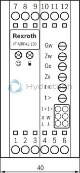
LED displays
|
|
Ready for operation (green) |
|
|
Enable (yellow) |
Potentiometer
|
Gw |
Amplitude attenuator |
|
Gx |
Sensitivity actual value |
|
Zw |
Zero point command value |
|
Zx |
Zero point actual value |
|
t <
|
Ramp time "Ramp up" |
|
t >
|
Ramp time "Ramp down" |
Measuring sockets
|
t <
|
Ramp time "Ramp up" |
|
t >
|
Ramp time "Ramp down" |
|
x |
Actual value |
|
w |
Command value |
|
⊥ |
Reference potential |
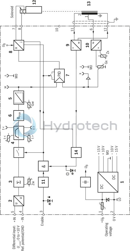
|
Zw |
Zero point command value |
|
Zx |
Zero point actual value |
|
t <
|
Ramp time "Ramp up" |
|
t >
|
Ramp time "Ramp down" |
|
Gw |
Amplitude attenuator |
|
Gx |
Sensitivity actual value |
|
w |
Command value |
|
x |
Actual value |
|
|
Ready for operation |
|
|
Enable |
|
1 |
Power supply unit |
|
2 |
Differential amplifier |
|
3 |
Command value summation |
|
4 |
Ramp generator |
|
5 |
Amplitude attenuator |
|
6 |
Amplitude limiter |
|
7 |
Valve position controller |
|
8 |
Power output stage |
|
9 |
Oscillator |
|
10 |
Demodulator |
|
11 |
Enable |
|
12 |
Proportional valve |
|
13 |
Position transducer |
|
14 |
Fault recognition |
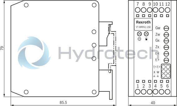
Dimensions in mm
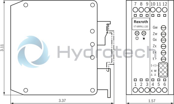
Dimensions in mm
The amplifier module may only be wired when de-energized.
Do not lay lines close to power cables.
Do not use free-wheeling diodes in the solenoid conductors.
The distance to aerial lines, radios, and radar systems has to be at least 1 m.
Always shield command value and position transducer lines; connect shielding to protective earthing (PE) on the module side.
In some cases (e.g. if PE is subject to strong interference) it can be necessary to connect the shield of the position transducer line directly to the LO of the amplifier module; other side open (risk of ground loops).
Recommendation: Also shield the solenoid conductors.
For solenoid conductors up to a length of 50 m, use cable type LiYCY 1.5 mm2.
For greater lengths, please contact us.
Do not connect terminal "earthing symbol" of the position transducer connector to "PE".
For switching command values, relays with gold-plated contacts have to be used (low voltages, low currents).
Only carry out measurements at the module using instruments with Ri > 100 kΩ.
With a strongly fluctuating operating voltage, it may in individual cases be necessary to use an external smoothing capacitor with a capacity of at least 2200 µF.
Recommendation:
Capacitor module VT 11110 (see data sheet 30750); sufficient for up to 3 amplifier modules
Notice:
When exchanging VT 11025, VT 11033 or VT 11034, please observe the different terminal assignment of the position transducer connector. Terminals 6 and 12 are swapped.
Setting information
Requirements: The system-specific circuitry must have been completed.
Zero point command value
Apply enable signal
Set the external command value presetting to zero
Set the internal command value to zero using the "Zw" zero point potentiometer and carry out a check at measuring socket "w"
Zero point actual value
Enable signal "OFF" or pull solenoid plug (valve moves to mechanical end position)
With potentiometer "Zx", set the actual value at measuring socket "x" to zero.
Ramp times
Set ramp time according to formula or table (see functional description "Ramp generator”) and check it at the "t >" and "t <" measuring sockets
Maximum values
Notice:
Before comparing the maximum value, the zero point must have been set correctly.
Externally preset a command value of 100 %
Set maximum control output using the "Gw" potentiometer and carry out a check at measuring socket "w"