

BOSCH REXROTH
R901044401
$32,780.16 USD
- BOSCH REXROTH
- Material:R901044401
- Model:SFS200A0-1-4X/
Quantity in stock: 0
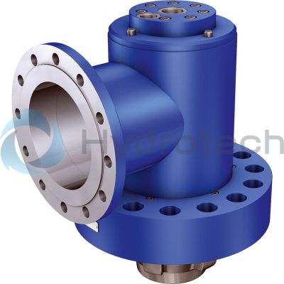
The Bosch Rexroth SFS200A0-1-4X (R901044401) is a high-performance industrial hydraulic valve designed for reliable blocking of oil flow at selected ports. This seat valve is pilot-operated, with a spool symbol for A and B ports, and is capable of handling a maximum pressure as specified in its product group ID. It features a number of ports suitable for various hydraulic circuits and utilizes hydraulic actuation for its operation. The SFS200A0-1-4X valve boasts a size that accommodates a significant max flow rate, ensuring efficient fluid control within the system. It employs a flange connection for secure installation and easy maintenance, with the connection diagram specifying the flange type according to EN standards. The valve is also equipped with multiple switching positions and has a weight that reflects its sturdy construction. Seals made from NBR (Nitrile Butadiene Rubber) are used in this model to ensure compatibility with various hydraulic fluids such as HL, HLP, HLPD, HVLP, HVLPD, and HFC. Additionally, the control port X can be either opened or closed depending on the application requirements. The hydraulically active switching prefill valve also includes a check valve feature for the flange connection. One of its notable capabilities is reduced switching noises thanks to end position cushioning effective on both sides of the valve. This design element not only minimizes operational noise but also contributes to optimized switching time characteristics, enhancing overall performance and reliability in demanding applications.
Size 200, A → B, hydraulically actuated
Industrial hydraulic valve in a high performance range. Reliable blocking of the oil flow at selected ports.
Unpacked Weight: 185.5 kg
Control port X: "Open" control port X1: "Close"
| Seat valve |
| Pilot-operated |
| Component series 4X |
| Maximum flow 14000 l/min |
| Size 200 … 300 |
| Maximum operating pressure 350 bar |
| Data Sheet | Download Data Sheet |
| 3D CAD | Download 3D CAD |
| Manual | Download Manual |
| Manual | Download Manual |
| Manual | Download Manual |
| Manual | Download Manual |
| Manual | Download Manual |
| Spool symbol | A → B |
| Max. pressure | 350 |
| Productgroup ID | 9,10,11,12,13,14 |
| Number of ports | 2 |
| Type of actuation | with hydraulic actuation |
| Size | 200 |
| Max. flow | 5600 |
| Type of connection | Flange connection |
| Connection diagram | Flange type 11 PN 16 according to EN 1092-1 |
| Number of switching positions | 2 |
| Weight | 185.5 |
| Seals | NBR |
| Hydraulic fluid | HL,HLP,HLPD,HVLP,HVLPD,HFC |
|
01 |
Prefill valves |
SFS |
|
02 |
Size |
200 |
|
250 |
||
|
300 |
||
|
03 |
Flange connection |
A |
|
04 |
without pre-decompression |
0 |
|
05 |
Main spool actively controllable |
1 |
|
06 |
Component series 40 to 49 (40 to 49: unchanged installation and connection dimensions) |
4X |
|
Seal material |
||
|
08 |
NBR seals |
no code |
|
Observe compatibility of seals with hydraulic fluid used. |
||
|
09 |
Further details in the plain text |
* |
|
01 |
02 |
03 |
04 |
05 |
06 |
07 |
08 |
|||
|
SFS |
A |
0 |
– |
1 |
– |
4X |
/ |
* |
general
|
Size |
200 | 250 | 300 | |
|
Weight |
kg |
190 | 380 | 655 |
|
Installation position |
any | |||
|
NG |
Maximum switching time in ms 1) |
|
|
Close |
Open |
|
|
ms |
ms |
|
| 200 | 60 | 70 |
| 250 | 70 | 80 |
| 300 | 110 | 90 |
| 1) | At X, X1 = 150 bar. The switching time depends on the line resistance, control valve and pilot flow. |
hydraulic
|
Size |
200 | 250 | 300 | ||
|
Maximum operating pressure |
Anschluss A |
bar |
16 | ||
|
Port B |
bar |
350 | |||
|
Anschluss X |
bar |
150 | |||
|
Anschluss X1 |
bar |
150 | |||
|
Maximum flow |
Case of application 1 |
l/min |
5600 | 10000 | 14000 |
|
Case of application 2 |
l/min |
4340 | 6775 | 9750 | |
|
Case of application 3 |
l/min |
3770 | 5890 | 8480 | |
|
Case of application 4 |
l/min |
1510 | 2360 | 3400 | |
|
Druckflüssigkeit |
Mineral oil (HL, HLP) to DIN 51524;fast bio-degradable hydraulic fluids according to VDMA 24568; HETG (rape seed oil); other hydraulic fluids on enquiry | ||||
|
Hydraulic fluid temperature range |
°C |
-30 … +80 | |||
|
Viscosity range |
mm²/s |
10 … 800 | |||
|
Maximum admissible degree of contamination of the hydraulic fluid 1) |
Class 20/18/15 according to ISO 4406 (c) | ||||
| 1) | The cleanliness classes specified for the components must be adhered to in hydraulic systems. Effective filtration prevents faults and simultaneously increases the life cycle of the components. For the selection of the filters, see www.boschrexroth.com/filter. |
Flow ‒ case of application 1 (A to B)
Flow ‒ case of application 2 (A to B)
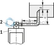
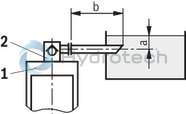
Size of the filling tank at least 1.5 x cylinder content
Flow ‒ case of application 3 (A to B)
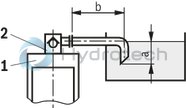
Flow ‒ case of application 4 (A to B)
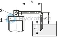
Information on case of application 1 to 4
For limit areas, please contact us. It is often enough, to select a pipeline which is one size larger.
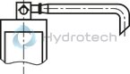
Attention!
An underdimensioned prefill valve and/or an underdimensioned line leads to gas leaks from the hydraulic fluid with corresponding consequences and often to long-term damage at the cylinder seals.
|
1 |
Cylinders |
|
2 |
Prefill valve |
|
a |
min. 300 mm with extended cylinder |
|
b |
up to 1000 mm with the specified maximum flows |
|
c |
≤ 500 mm |
|
h |
300 mm ≤ h < 500 mm |
For applications outside these parameters, please consult us!

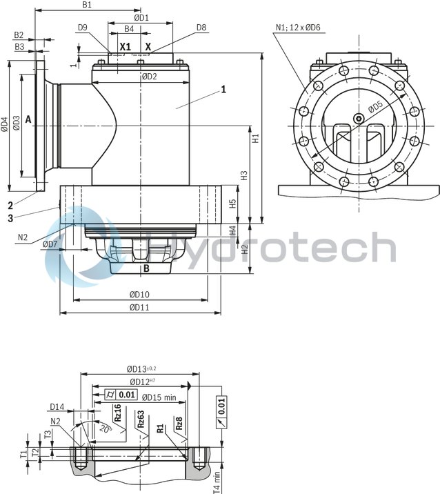
Dimensions in mm
|
1 |
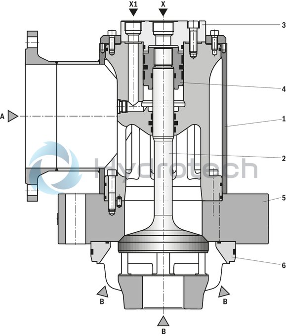
Housing installation continuously rotatable by 360° |
|
2 |
Flange according to EN 1092-1/11.../PN16 |
|
3 |
Name plate |
|
T2 |
Depth of fit |
|
N2 |
Number of the valve mounting screws evenly arranged at the circumference (separate order) The following valve mounting screws are recommended: Hexagon socket head cap screws ISO 21269 - 10.9 friction coefficient μtotal = 0.12 to 0.17 |
Number of the valve mounting screws evenly arranged at the circumference (separate order)
The following valve mounting screws are recommended:
Hexagon socket head cap screws ISO 21269 - 10.9
friction coefficient μtotal = 0.12 to 0.17
|
NG |
Dimensions in mm |
Tightening torqueMA in Nm |
|
200 |
M36 x 3 x 150 |
3100 |
|
250 |
M42 x 3 x 180 |
5100 |
|
300 |
M42 x 3 x 220 |
5100 |
|
NG |
B1 |
B2 |
B3 |
B4 |
ØD1 |
ØD2 |
ØD3 |
ØD4 |
ØD5 |
ØD6 |
ØD7 |
D8 |
D9 |
ØD10 |
ØD11 |
ØD12 |
ØD13 |
ØD14 |
ØD15 |
H1 |
H2 |
H3 |
H4 |
H5 |
N1 |
N2 |
T1 |
T2 |
T3 |
T4 |
R1 |
|
mm |
mm |
mm |
mm |
mm |
mm |
mm |
mm |
mm |
mm |
mm |
mm |
mm |
mm |
mm |
mm |
mm |
mm |
mm |
mm |
mm |
mm |
mm |
mm |
mm |
mm |
mm |
mm |
||||
| 200 | 275 | 24 | 3 | 60 | 168 | 273 | 268 | 340 | 295 | 22 | 40 | G1 1/4 | 350 | 420 | 290 | 350 | M36 x 3 | 270 | 445 | 180 | 255 | 35 | 100 | 12 | 15 | 37 | 26 | 5 | 50 | 3 | |
| 250 | 330 | 26 | 3 | 80 | 225 | 356 | 320 | 405 | 355 | 26 | 46 | G1 1/2 | G1 1/4 | 445 | 530 | 380 | 445 | M42 x 3 | 355 | 571 | 240 | 320 | 55 | 120 | 12 | 18 | 57 | 42 | 8 | 60 | 5 |
| 300 | 380 | 28 | 4 | 94 | 250 | 419 | 378 | 460 | 410 | 26 | 46 | G1 1/2 | G1 1/4 | 525 | 610 | 450 | 525 | M42 x 3 | 425 | 684 | 305 | 390 | 55 | 160 | 12 | 24 | 57 | 42 | 8 | 75 | 5 |
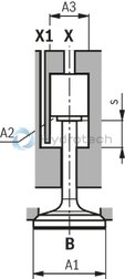
Poppet geometry and determination of the minimum pilot pressure
|
A1 |
Effective area of the main poppet |
|
A2 |
Effective area of the control spool "closing" |
|
A3 |
Effective area of the control spool "opening" |
|
s |
Piston stroke |
|
V1 |
Pilot volume for opening the valve |
|
V2 |
Pilot volume for closing the valve |
|
pSt |
Pilot pressure at port X |
|
pB |
Operating pressure at port B |

|
|
NG |
A1 |
A2 |
A3 |
s |
V1 |
V2 |
Unchecking ratio |
|
cm² |
cm² |
cm² |
mm |
cm³ |
cm³ |
||
| 200 | 216.4 | 36.4 | 50.3 | 42 | 211 | 153 | 4.3 |
| 250 | 373.3 | 67.4 | 95 | 52.5 | 503.7 | 353.8 | 3.9 |
| 300 | 572.6 | 92.86 | 143.1 | 63 | 901.8 | 585 | 4 |
Example: Type SFS 200 A0...
pB = 30 bar;
pSt = 4.3 x 30 bar = 129 bar