

BOSCH REXROTH
R900917786
$3,069.36 USD
- BOSCH REXROTH
- Material:R900917786
- Model:3DR10P5-6X/100Y/00V
Quantity in stock: 0
The Bosch Rexroth 3DR10P5-6X/100Y/00V (R900917786) is a sophisticated pressure valve designed for precise control of hydraulic system pressures. This pilot-operated way pressure reducing valve is integral in managing the reduction and limitation of secondary circuit pressures. With its main valve featuring a control spool and a pilot control valve that includes a pressure adjustment element, this product ensures efficient operation and reliable performance. In its default state, the valve permits unrestricted flow from channel P to A, maintaining system functionality. The pressure in channel A is regulated through a bore impacting the piston area, which is counterbalanced by a compression spring. The nozzle directs pressure to control the spool's spring-loaded side, while the ball within the pilot control valve responds to compression spring settings. This interaction allows hydraulic fluid to flow until the pressure in channel A surpasses the set value, causing the ball to open and adjust the spool position. The 3DR10P5-6X/100Y/00V maintains desired pressure levels by equalizing channel A's pressure with that of the compression spring setting. Should external forces increase this pressure, the control spool adjusts against the spring, linking channel A with T and allowing excess fluid to return to the tank, preventing further increases. This model includes an external pilot oil return via port Y that must be connected depressurized to ensure proper function. Additionally, there's a provision for monitoring reduced pressure via a gauge connection on channel A. Designed for subplate mounting with compatibility for DIN form A, ISO standards, and CETOP RP 121 H guidelines (subplates ordered separately), this valve offers versatility in installation and use. It comes with various adjustment elements such as rotary knobs and lockable versions with scales for precise calibration. With its robust construction capable of handling maximum operating pressures up to bar and flow rates up to l/min, this Bosch Rexroth valve stands as an essential component for advanced hydraulic systems requiring meticulous pressure management.
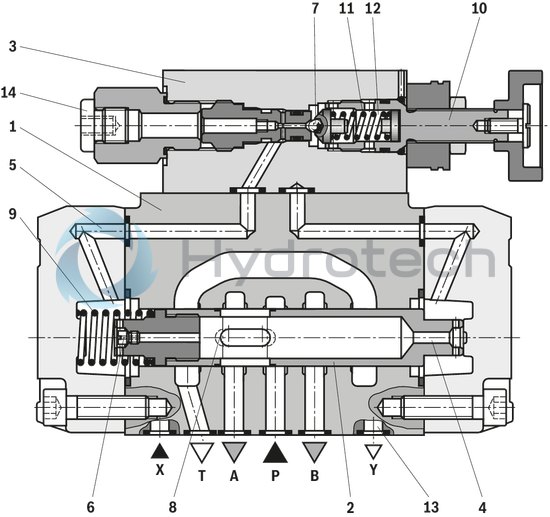
The pressure valve type 3DR is a pilot-operated 3-way pressure reducing valve with pressure limitation of the secondary circuit. It is used to reduce the system pressure.
The pressure reducing valve basically consists of the main valve (1) with control spool (2) and pilot control valve (3) with pressure adjustment element (10).
The valve is open in initial position. Hydraulic fluid can flow from channel P to channel A without restrictions. The pressure in channel A is simultaneously applied via the bore (4) at the piston area opposite the compression spring (9). Simultaneously, pressure is applied via the nozzle (6) to the spring-loaded side of the control spool (2) and via channel (5) to
ball (7) in the pilot control valve (3). Depending on the setting of the compression spring (11), pressure builds up upstream of the ball (7) and in channel (5) holding the control spool (2) in open position. Hydraulic fluid flows from channel P via the control spool (2) to channel A until a pressure builds up in channel A exceeding the pressure value set at the compression spring (11) and opening the ball (7).
The control spool (2) moves to closed position. The desired reduced pressure is reached if there is a balance between the pressure in channel A and the pressure value set at the compression spring (11).
If the pressure in channel A increases further due to an external force effect at the actuator, the control spool (2) is pushed further against the compression spring (9). In this way, channel A is connected to channel T via the control edge (8) at the control spool (2). So much hydraulic fluid is discharged into the tank that the pressure can no longer increase. The pilot oil return from the spring chamber (12) is always realized externally via the control line (13) at port Y. A depressurized connection to the tank must always be ensured.
The pressure gauge connection (14) enables control of the reduced pressure in channel A.
Type 3DR 10 P4–6X/…
|
01 |
02 |
03 |
04 |
05 |
06 |
07 |
08 |
09 |
10 |
|||
|
3DR |
10 |
P |
– |
6X |
/ |
Y |
/ |
00 |
* |
|
01 |
3-way pressure reducing valve |
3DR |
|
02 |
Size 10 |
10 |
|
03 |
Subplate mounting |
P |
|
Adjustment element |
||
|
04 |
Rotary knob |
4 |
|
Sleeve with hexagon and protective cap |
5 |
|
|
Lockable rotary knob with scale |
6 1) |
|
|
Rotary knob with scale |
7 |
|
|
05 |
Series 60 to 69 (60 to 69: unchanged installation and connection dimensions) |
6X |
|
06 |
Set pressure up to 50 bar |
50 |
|
Set pressure up to 100 bar |
100 |
|
|
Set pressure up to 200 bar |
200 |
|
|
Set pressure up to 315 bar |
315 |
|
|
Pilot oil flow |
||
|
07 |
Internal pilot oil supply, external pilot oil return |
Y |
|
08 |
With stroke limitation |
00 |
|
09 |
NBR seals |
M |
|
FKM seals (other seals upon request) |
V |
|
|
Observe compatibility of seals with hydraulic fluid used. |
||
|
10 |
Further details in the plain text |
* |
| 1) H-key with material no. 00008158 is included in the scope of delivery. |
Preferred types and standard units are specified in the EPS (standard price list).
general
|
Size |
10 | |
|
Weight |
kg |
6 |
|
Installation position |
any | |
|
Direction of flow |
see symbol | |
|
Ambient temperature range |
°C |
-30 … +50 |
hydraulic
|
Size |
10 | ||
|
Nominal pressure |
bar |
315 | |
|
Maximum operating pressure |
Port P |
bar |
315 |
|
Anschluss A |
bar |
315 | |
|
Port Y |
separate and depressurized to the tank | ||
|
Set pressure |
Minimum |
flow-dependent, see characteristic curves | |
|
Maximum |
bar |
50 100 200 315 |
|
|
Maximum flow |
l/min |
120 | |
|
Hydraulic fluid |
see table | ||
|
Hydraulic fluid temperature range |
NBR seals |
°C |
-30 … +80 |
|
FKM seals |
°C |
-20 … +80 | |
|
Viscosity range |
mm²/s |
10 … 800 | |
|
Maximum admissible degree of contamination of the hydraulic fluid |
Class 9 according to NAS 1638. For this, we recommend using a filter with a minimum retention rate of β10 ≥ 75. | ||
|
Hydraulic fluid |
Classification |
Suitable sealing materials |
Standards |
|
|
Mineral oil |
HL, HLP |
FKM, NBR |
DIN 51524 |
|
|
Bio-degradable |
Insoluble in water |
HEES (synthetic esters) |
FKM |
VDMA 24568 |
|
HETG (rape seed oil) |
FKM, NBR |
|||
|
Soluble in water |
HEPG (polyglycols) |
FKM |
VDMA 24568 |
|
|
Other hydraulic fluids on request |
||||
| 1) Suitable for NBR and FKM seals | |
| 2) Suitable for FKM seals only |
For applications outside these parameters, please consult us!
(measured at v = 41 mm2/s and ϑ = 50 °C)
Outlet pressure pA dependent on the flow qV
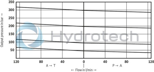
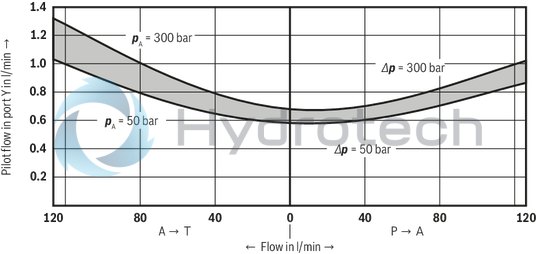
The characteristic curves apply for outlet pressurepT = zero in the entire flow range.
Flow resistance
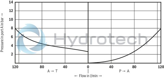
Minimum set pressure pmin dependent on the flow qV
The characteristic curves apply for outlet pressure pT = zero in the entire flow range.
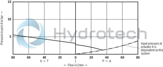
Pilot flow qV st dependent on the flow qV

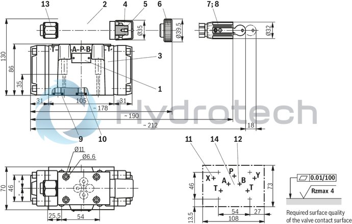
Dimensions in mm
|
1 |
Name plate |
|
2 |
Pilot control valve |
|
3 |
Main valve |
|
4 |
Adjustment element "5" |
|
5 |
Hexagon SW10 |
|
6 |
Adjustment element "4" |
|
7 |
Adjustment element "6" |
|
8 |
Adjustment element "7" |
|
9 |
O-rings 10.82 x 1.78 for ports X and Y |
|
10 |
O-rings 12 x 2 for ports A, B, P and T |
|
11 |
Port X must be closed in the subplate |
|
12 |
Port B must be closed in the subplate |
|
13 |
Pressure gauge connection |
|
14 |
Valve contact surface, porting pattern according to DIN 24 340 form A, ISO 4401 and CETOP-RP 121 H Subplates G535/01 (G 3/4) G536/01 (G 1) must be ordered separately. Valve mounting screws 4 x M6 x 45 DIN 912-10.9, MA = 15,5 Nm, must be ordered separately. |