


BOSCH REXROTH
R900703811
$3,181.00 USD
- BOSCH REXROTH
- Material:R900703811
- Model:VT-DFP-A-2X/G24K0/0/V GO2
Quantity in stock: 0
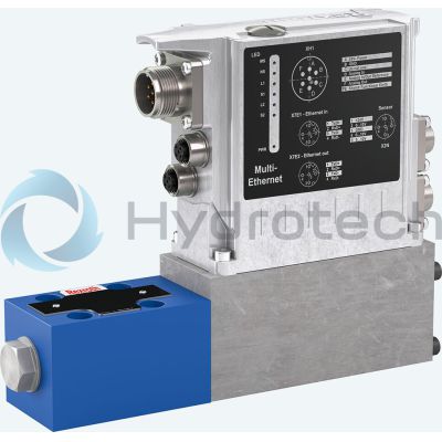
The Bosch Rexroth VT-DFP-A-2X/G24K0/0/V (R900703811) is a sophisticated pilot valve designed for precise pressure and flow control within hydraulic systems, specifically tailored for the SYDFE system. This model is part of the component series X and is characterized by its analog communication capabilities. It operates through a proportional solenoid which benefits from electrical feedback, ensuring accurate and responsive control. This pilot valve boasts a robust design that can withstand a maximum operating pressure of bar, catering to demanding applications that require reliable performance under high-pressure conditions. The VT-DFP-A-2X/G24K0/0/V is displacement type variable, which allows for fine-tuned adjustments to the hydraulic flow, enhancing the efficiency and precision of the system it is integrated with. Additionally, this model is equipped with control electronics VTDFP that are intended for use with the SYHDFE external control electronics VT X. This feature allows for seamless integration with existing systems and ensures compatibility with external control units, providing users with flexibility in system design and upgrades. The product falls under Bosch Rexroth's product group ID ,,,, and has an unspecified weight. As a pilot valve, it plays a crucial role in hydraulic applications by controlling the operation of main valves. Its reliability and precision make it an essential component in various hydraulic control systems where accurate flow regulation is paramount. In summary, the Bosch Rexroth VT-DFP-A-2X/G24K0/0/V (R900703811) stands out as a high-quality pilot valve offering precise control for complex hydraulic systems. Its compatibility with SYDFE and SYHDFE systems, along with its variable displacement type and robust construction for high-pressure environments, makes it suitable for specialized industrial applications requiring meticulous flow management.
Unpacked Weight: 1.96 kg
| Communication: analog |
| Pilot valve for SYDFE1 - system |
| Component series 2X |
| Nominal pressure 350 bar |
| Nominal pressure 350 bar |
| Nominal pressure 350 bar |
| Data Sheet | Download Data Sheet |
| Displacement type | variable |
| Productgroup ID | 9,10,11,12,13,14 |
| Weight | 1.96 |
|
01 |
02 |
03 |
04 |
05 |
06 |
07 |
08 |
09 |
10 |
11 |
||||||
|
VT-DFP |
- |
- |
2X |
/ |
G24 |
K0 |
/ |
/ |
- |
* |
|
Series |
|||||||
|
01 |
Pilot valve for external electronics |
VT-DFP |
|||||
|
Spool design |
|||||||
|
02 |
Standard (not for HFC fluids) |
A |
|||||
|
2-groove spool (only for replacement requirement) |
B |
||||||
|
4-groove spool (e.g. for HFC fluids) |
C |
||||||
|
03 |
Component series |
2X |
|||||
|
04 |
Direct voltage 24 V |
G24 |
|||||
|
05 |
Connector (without mating connector) 1) |
K0 |
|||||
|
Installation orientation connector (VT-DFP) and/or integrated electronics (see also comment on feature 6) |
|||||||
|
06 |
radially to the pump axis |
0 |
|||||
|
folded 90° in the direction of the subplate with counterclockwise direction of rotation |
1 |
||||||
|
folded 90° in the direction of the subplate with clockwise direction of rotation |
2 |
||||||
|
Additional functions: Closed-loop control |
A |
B |
C |
D |
R |
||
|
07 |
(without) |
||||||
|
Electronics assembly, option |
|||||||
|
08 |
(without) |
||||||
|
Actual pressure value input |
Plug-in connector |
||||||
|
09 |
(without) |
||||||
|
10 |
FKM seals suitable for mineral oils (HL, HLP) according to DIN 51524 and HFC fluids 2) |
V |
|||||
|
11 |
Further details in the plain text e. g. SO variant |
* |
|||||
|
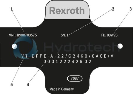
1 |
Material number |
|
2 |
Serial number |
|
3 |
Date of production |
|
4 |
Production order number |
|
5 |
Type designation |
|
● |
available |
|
- |
not available |
Note on feature 6: Installation orientation of the valve electronics
|
Clockwise direction of rotation, installation orientation 0 |
Clockwise direction of rotation, installation orientation 2 |
Counterclockwise direction of rotation, installation orientation 0 |
Counterclockwise direction of rotation, installation orientation 1 |

|

|

|

|
| 1) | Connector dependent on the valve type (see "Technical data" and "Electrical connection”). |
| 2) | With the SY(H)DFEn control system with analog interfaces, the plug-in connector X2 can not be used as actual pressure value input. Thus, a separate pressure transducer has to be used and connected to plug-in connector X1 in this case. |
| 3) | Only in connection with SYHDFE and spool design C (feature 2). |
|
1 |
Material number |
|
2 |
Serial number |
|
3 |
Date of production |
|
4 |
Production order number |
|
5 |
Type designation |
|
● |
available |
|
- |
not available |
Accessories
Version 10/2011, enquire availability
Notice:
For information on the environment simulation testing for the areas of EMC (electro-magnetic compatibility), climate and mechanical load, see data sheet 30030-U.
mechanic and hydraulic
|
Mass |
Pump without through-drive incl. pilot valve |
m |
kg |
1.96 |
|
Hydraulic fluid |
Mineral oil (HL, HLP) according to DIN 51524; HFC fluids only in connection with SYHDFE control system and C spool design C (feature 2 of ordering code) | |||
|
Hydraulic fluid temperature range |
ϑ |
°C |
-20 … +70 | |
|
Maximum admissible degree of contamination of the hydraulic fluid according to ISO 4406 |
Class 18/16/13 (for particle size ≤ 4/6/14 μm) | |||
mechanic and hydraulic
|
Weight without filling quantity |
m |
kg |
1.96 |
|
Hydraulic fluid |
Mineral oil (HL, HLP) according to DIN 51524; HFC fluids only in connection with SYHDFE control system and C spool design C (feature 2 of ordering code) | ||
|
Hydraulic fluid temperature range |
ϑ |
°C |
-20 … +70 |
|
Maximum admissible degree of contamination of the hydraulic fluid according to ISO 4406 |
Class 18/16/13 (for particle size ≤ 4/6/14 μm) | ||
electrical
|
Operating voltage |
UB |
see VT5041-3X | ||
|
Inputs |
Actual pressure value input X1; |
U or I |
see VT5041-3X | |
|
Analog current inputs, load |
RB |
see VT5041-3X | ||
|
Analog voltage inputs |
RE |
see VT5041-3X | ||
|
Digital inputs |
Logic 0 |
see VT5041-3X | ||
|
Logic 1 |
see VT5041-3X | |||
|
Outputs |
pactual / UOUT1 |
UO |
see VT5041-3X | |
|
Imax |
see VT5041-3X | |||
|
αactual / UOUT2 |
UO |
see VT5041-3X | ||
|
Imax |
see VT5041-3X | |||
|
Digital outputs |
Logic 0 |
see VT5041-3X | ||
|
Logic 1 |
see VT5041-3X | |||
|
Ambient temperature range at the pump |
ϑ |
°C |
-20 … +60 | |
|
Storage temperature range (pump + electronics) |
ϑ |
°C |
-20 … +70 | |
|
Type of protection according to EN 60529 |
Pump incl. pilot valve |
IP65 with mounted and locked plug-in connectors | ||
mechanisch und hydraulisch
|
Weight without filling quantity |
m |
kg |
1.96 |
|
Hydraulic fluid |
Mineral oil (HL, HLP) according to DIN 51524; HFC fluids only in connection with SYHDFE control system and C spool design C (feature 2 of ordering code) | ||
|
Hydraulic fluid temperature range |
ϑ |
°C |
-20 … +70 |
|
Maximum admissible degree of contamination of the hydraulic fluid according to ISO 4406 |
Class 18/16/13 (for particle size ≤ 4/6/14 μm) | ||
elektrisch
|
Operating voltage |
UB |
see VT5041-3X | ||
|
Inputs |
Actual pressure value input X1; |
U or I |
see VT5041-3X | |
|
Analog current inputs, load |
RB |
see VT5041-3X | ||
|
Analog voltage inputs |
RE |
see VT5041-3X | ||
|
Digital inputs |
Logic 0 |
see VT5041-3X | ||
|
Logic 1 |
see VT5041-3X | |||
|
Outputs |
nactual / UOUT1 |
UO |
see VT5041-3X | |
|
Imax |
see VT5041-3X | |||
|
αactual / UOUT2 |
UO |
see VT5041-3X | ||
|
Imax |
see VT5041-3X | |||
|
Digital outputs |
Logic 0 |
see VT5041-3X | ||
|
Logic 1 |
see VT5041-3X | |||
|
Ambient temperature range at the pump |
ϑ |
°C |
-20 … +60 | |
|
Storage temperature range (pump + electronics) |
ϑ |
°C |
-20 … +70 | |
|
Type of protection according to EN 60529 |
Pump incl. pilot valve |
IP65 with mounted and locked plug-in connectors | ||
elektrisch
|
Operating voltage |
UB |
see VT5041-3X | ||
|
Inputs |
Actual pressure value input X1; |
U or I |
see VT5041-3X | |
|
Analog current inputs, load |
RB |
see VT5041-3X | ||
|
Analog voltage inputs |
RE |
see VT5041-3X | ||
|
Digital inputs |
Logic 0 |
see VT5041-3X | ||
|
Logic 1 |
see VT5041-3X | |||
|
Outputs |
pactual / UOUT1 |
UO |
see VT5041-3X | |
|
Imax |
see VT5041-3X | |||
|
αactual / UOUT2 |
UO |
see VT5041-3X | ||
|
Imax |
see VT5041-3X | |||
|
Digital outputs |
Logic 0 |
see VT5041-3X | ||
|
Logic 1 |
see VT5041-3X | |||
|
Ambient temperature range at the pump |
ϑ |
°C |
-20 … +60 | |
|
Storage temperature range (pump + electronics) |
ϑ |
°C |
-20 … +70 | |
|
Type of protection according to EN 60529 |
Pump incl. pilot valve |
IP65 with mounted and locked plug-in connectors | ||
mechanisch und hydraulisch
|
Mass |
Pump without through-drive incl. pilot valve |
m |
kg |
1.96 |
|
Hydraulic fluid |
Mineral oil (HL, HLP) according to DIN 51524; HFC fluids only in connection with SYHDFE control system and C spool design C (feature 2 of ordering code) | |||
|
Hydraulic fluid temperature range |
ϑ |
°C |
-20 … +70 | |
|
Maximum admissible degree of contamination of the hydraulic fluid according to ISO 4406 |
Class 18/16/13 (for particle size ≤ 4/6/14 μm) | |||
elektrisch
|
Operating voltage |
UB |
see VT5041-3X | ||
|
Inputs |
Actual pressure value input X1; |
U or I |
see VT5041-3X | |
|
Analog current inputs, load |
RB |
see VT5041-3X | ||
|
Analog voltage inputs |
RE |
see VT5041-3X | ||
|
Digital inputs |
Logic 0 |
see VT5041-3X | ||
|
Logic 1 |
see VT5041-3X | |||
|
Outputs |
pactual / UOUT1 |
UO |
see VT5041-3X | |
|
Imax |
see VT5041-3X | |||
|
αactual / UOUT2 |
UO |
see VT5041-3X | ||
|
Imax |
see VT5041-3X | |||
|
Digital outputs |
Logic 0 |
see VT5041-3X | ||
|
Logic 1 |
see VT5041-3X | |||
|
Ambient temperature range at the pump |
ϑ |
°C |
-20 … +60 | |
|
Storage temperature range (pump + electronics) |
ϑ |
°C |
-20 … +70 | |
|
Type of protection according to EN 60529 |
Pump incl. pilot valve |
IP65 with mounted and locked plug-in connectors | ||
For applications outside these parameters, please consult us!
For external analog electronics
Details on the electrical connection to the VT 5041-3X amplifier are described in data sheet 30242.
Solenoid
Mating connector 3-pole Z4 M SW according to DIN EN 175301-803 (separate order see Accessories)
Mating connector 4-pole Pg7-G4W1F/Pg7 SW (separate order see Accessories)
Dimensions in mm

Valve mounting screws for all types:
4 hexagon socket head cap screws
ISO4762-M6X40-10.9-flZn-240h-L,
friction coefficient μtotal = 0.09 to 0.14 according to VDA 235-101,
Tightening torque MA = 7 Nm,
material number: R913000058
Amending notes on the SY(H)DFE control systems can be found in the operating instructions (see section “Further information about this control system”).