


BOSCH REXROTH
R900590053
$2,357.71 USD
- BOSCH REXROTH
- Material:R900590053
- Model:Z4WH10E63-4X/
Quantity in stock: 0
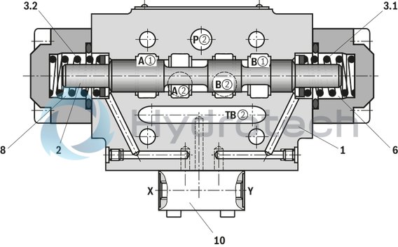
The Bosch Rexroth Z4WH10E63-4X/ (R900590053) is a high-performance directional spool valve designed for hydraulic operations. This pilot-operated valve offers exceptional control for start, stop, and directional functions of the hydraulic flow. It is capable of functioning as a shutoff valve or facilitating a shutoff short circuit through the valve while ensuring P and T ports free flow in every spool position. The porting pattern adheres to ISO standards, guaranteeing compatibility and ease of integration into various hydraulic systems. Equipped with wet-pin DC or AC solenoids that can be selected based on application requirements, this valve also provides the flexibility of optional auxiliary operating devices. The electrical connection is designed to accommodate either individual or central connections, as detailed in RE specifications. For applications requiring precise control, optional features such as switching time adjustment and stroke setting at the main spool are available. Additionally, for enhanced operational monitoring, the Z4WH10E63-4X/ can be fitted with inductive position switches and proximity sensors that offer contactless detection. With its robust design, this component from Bosch Rexroth's series X can withstand a maximum operating pressure (bar) and maximum flow (l/min) that align with demanding industrial applications. Whether it's for mobile machinery or stationary industrial equipment, this directional spool valve ensures reliability and precision in controlling hydraulic systems.
Size 10, symbol E63, with hydraulic actuation,
Industrial hydraulic valve in the medium performance range. Reliable switching of the oil flow direction according to hydraulic symbol
Unpacked Weight: 3.58 kg
| Spool valve |
| Pilot-operated |
| External pilot oil supply, external pilot oil return |
| without manual override |
| Component series 4X |
| Maximum flow 160 l/min |
| Size 10 |
| Maximum operating pressure 315 bar |
| Data Sheet | Download Data Sheet |
| Manual | Download Manual |
| Spool symbol | Symbol E63 |
| Max. pressure | 315 |
| Productgroup ID | 9,10,11,12,13,14 |
| Number of ports | 4 |
| Type of actuation | with hydraulic actuation |
| Size | 10 |
| Max. flow | 160 |
| Type of connection | Sandwich plate |
| Connection diagram NFPA | NFPA T3.5.1 R2-2002 D05 |
| Size_CETOP | D05 |
| Connection diagram | ISO 4401-05-04-0-05 |
| Number of switching positions | 2 |
| Weight | 3.58 |
| Seals | NBR |
| Hydraulic fluid | HL,HLP,HETG |
|
AC voltage mains (admissible voltage tolerance ± 10%) |
Nominal voltage of the DC solenoid in case of operation with alternating voltage |
Ordering code |
|
110 V - 50/60 Hz 120 V - 60 Hz |
96 V |
G96 |
|
230 V - 50/60 Hz |
205 V |
G205 |
|
01 |
02 |
03 |
04 |
05 |
06 |
07 |
08 |
09 |
10 |
11 |
12 |
13 |
14 |
||
|
Z4 |
WH |
10 |
– |
4X |
/ |
* |
|
01 |
Z4 |
|
|
Type of actuation |
||
|
02 |
hydraulic |
WH |
|
03 |
Size 10 |
10 |
|
04 |
Symbols see symbols |
|
|
05 |
Component series 40 to 49 (40 to 49: unchanged installation and connection dimensions) |
4X |
|
06 |
Without manual override |
no code |
|
07 |
External pilot oil supply, external pilot oil return |
no code |
|
08 |
Without switching time adjustment |
no code |
|
Switching time adjustment as supply control |
S |
|
|
Switching time adjustment as discharge control |
S2 |
|
|
Spool position monitoring |
||
|
09 |
Without position switch |
no code |
|
Monitored spool position "a" |
QMAG24 |
|
|
Monitored spool position "b" |
QMBG24 |
|
|
Monitored spool position "a" and "b" |
QMABG24 |
|
|
10 |
No additional details |
Without slash |
|
Additional details |
/ |
|
|
Stroke setting |
||
|
11 |
Without stroke setting |
no code |
|
Stroke setting on side A and B |
no code |
|
|
Stroke setting on side A |
11 |
|
|
Stroke setting on side B |
12 |
|
|
For more information, see stroke setting, mounting options |
||
|
12 |
Without pressure reducing valve |
no code |
|
Seal material |
||
|
13 |
NBR seals |
no code |
|
FKM seals |
V |
|
|
Other seals on request |
||
|
Observe compatibility of seals with hydraulic fluid used. |
||
|
14 |
Further details in the plain text |
* |
Preferred types and standard units are contained in the EPS (standard price list).
general
|
Size |
10 | ||
|
Weight |
Valve with one solenoid |
kg |
4.2 |
|
Valve with two solenoids |
kg |
4.6 | |
|
Valve witch hydraulic actuation |
kg |
3.5 | |
|
Switching time adjustment |
kg |
0.8 | |
|
3-way pressure reducing valve |
kg |
0.4 | |
|
Plate for version "T" |
kg |
0.5 | |
|
Installation position |
any | ||
|
Ambient temperature ranges (NBR seals) |
°C |
-30 … +50 | |
|
Ambient temperature ranges (FKM seals) |
°C |
-20 … +50 | |
hydraulic
|
Size |
10 | |||
|
Maximum operating pressure |
Port P |
External pilot oil supply |
bar |
315 |
|
Internal pilot oil supply (without pressure reducing valve) |
bar |
250 | ||
|
Internal pilot oil supply (with pressure reducing valve) |
bar |
315 | ||
|
Anschluss A |
bar |
315 | ||
|
Port B |
bar |
315 | ||
|
Port T |
with DC solenoid |
bar |
210 | |
|
with AC solenoid |
bar |
160 | ||
|
Maximum flow |
l/min |
160 | ||
|
Minimum pilot pressure |
bar |
12 | ||
|
Pilot volume for switching process |
cm³ |
1.3 | ||
|
Hydraulic fluid 1) |
see table | |||
|
Hydraulic fluid temperature range (NBR seals) |
°C |
-30 … +80 | ||
|
Hydraulic fluid temperature range (FKM seals) |
°C |
-20 … +80 | ||
|
Viscosity range |
mm²/s |
2.8 … 500 | ||
|
Maximum admissible degree of contamination of the hydraulic fluid 2) |
Class 20/18/15 according to ISO 4406 (c) | |||
| 1) | The ignition temperature of the process and operating medium used must be over the maximum solenoid surface temperature. |
| 2) | The cleanliness classes specified for the components must be adhered to in hydraulic systems. Effective filtration prevents faults and simultaneously increases the life cycle of the components. For the selection of the filters, see www.boschrexroth.com/filter. |
|
Hydraulic fluid |
Classification |
Suitable sealing materials |
Standards |
|
|
Mineral oil |
HL, HLP |
NBR, FKM |
DIN 51524 |
|
|
Fast bio-degradable hydraulic fluids |
VDMA 24568 |
|||
|
Environmentally compatible |
Insoluble in water |
HETG |
NBR, FKM |
|
|
HEES |
FKM |
|||
|
Soluble in water |
HEPG |
NBR, FKM |
||
|
Other hydraulic fluids on request |
||||
Notes!
Actuation of the manual override is only possible up to a tank pressure of approx. 50 bar. Avoid damage to the bore of the manual override! (Special tool for actuation, separate order, material no. R900024943). When the manual override is blocked, the operation of the solenoid must be prevented! The simultaneous actuation of the solenoids must be prevented!Inductive position switch type QM: electrical connection
The electric connection is realized via a 4-pole mating connector (separate order) with connection thread M12 x 1.
electrical
|
Connection voltage (DC voltage) |
V |
24 | ||
|
Voltage tolerance (connection voltage) |
+30 %/-15 % | |||
|
Admissible residual ripple |
% |
≤ 10 | ||
|
Max. load capacity |
mA |
400 | ||
|
Switching outputs 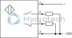
|
PNP transistor outputs, load between switching outputs and GND | |||
|
Pinout 
|
1 |
V |
24 | |
|
2, 4 |
Switching output |
mA |
400 | |
|
3 |
Earthing (GND) |
V |
0 | |
For applications outside these parameters, please consult us!
(measured with HLP46, ϑOil = 40 ±5 °C)
Δp-qV characteristic curves
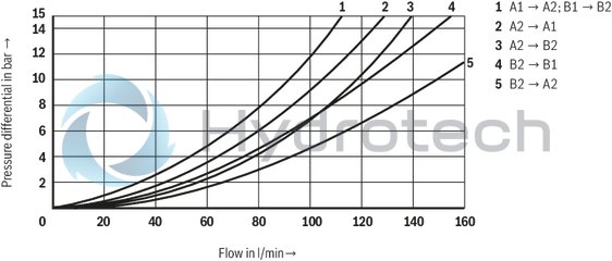
E62
Version "no code"
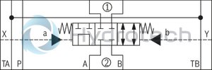
E63
Version "no code"
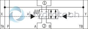
E68
Version "no code"
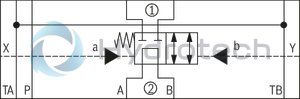
E501)
Version "no code"
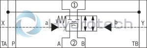
| 1) | Opening cross-section in spool position "a" (A2 → B2) = 50 mm2 |
E51
Version "no code"
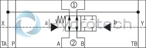
E521)
Version "no code"
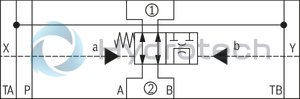
| 1) | Opening cross-section in spool position "b" (A2 → B2) = 35 mm2 |
|
➀ |
component side |
|
➁ |
plate side |
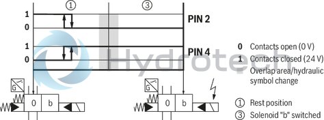
Inductive position switch type QM Switching logics
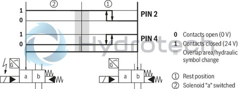
Version QMA
(Position switch on side B, monitored spool position of the main stage "a")
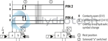
Version QMA
(Position switch on side B, monitored spool position of the main stage "a")
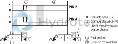
Version QMB
(Position switch on side A, monitored spool position of the main stage "b")
Version QMB
(Position switch on side A, monitored spool position of the main stage "b")
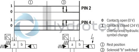
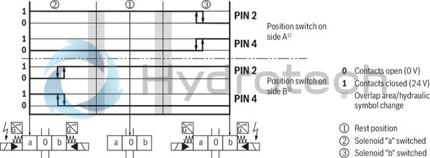
version QMAB
(Position switch on side A and B, monitored spool position "a" and "b")
Version QM0
(Position switch on side A and B, monitored spool position "0")
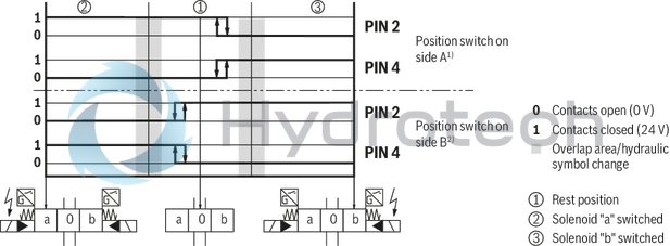
| 1) No signal change at the position switch on side B with spool position "a" | |
| 2) No signal change at the position switch on side A with spool position "b" |
Version QM0
(Position switch on side B, monitored spool position of the main stage "0")
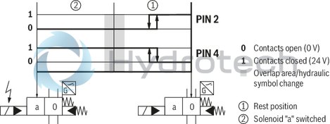
Version QM0
(Position switch on side A, monitored spool position of the main stage "0")
Dimensions in mm
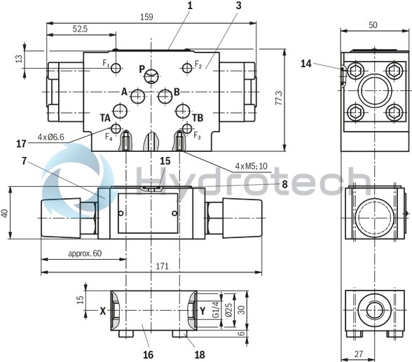
|
1 |
Name plate complete valve |
|
3 |
Main valve |
|
7 |
Switching time adjustment (throttle check valve); dependent on supply or discharge control installation position (representation: supply control) |
|
8 |
R-ring plate |
|
14 |
Identical seal rings for ports A, B, P, TA and TB |
|
15 |
Identical seal rings for ports A, B, P and T |
|
16 |
Pilot oil subplate |
|
17 |
Valve mounting bores Valve mounting screws (separate order) 4 hexagon socket head cap screws ISO 4762 - M6 - 10.9 |
|
18 |
Valve mounting screws (separate order)4 hexagon socket head cap screws ISO 4762 - M5 - 10.9 |
|
Mounting options |
L1 |
L2 |
|
mm |
mm |
|
| Stroke setting on side A and B | 95 | 149 |
| Stroke setting on side A | 95 | - |
| Stroke setting on side B | - | 149 |
Notice!
Length and tightening torque of the valve mounting screws must be calculated according to the components mounted.
The stroke of the main spool is limited by the stroke setting.
The piston stroke is shortened by untightening the lock nut (17) and clockwise rotation of the adjustment spindle (18). For this, the control chamber has to be depressurized.
Stroke 6 mm (1 rotation = 1 mm stroke)
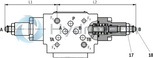
|
17 |
Lock nut SW27 |
|
18 |
Adjustment spindle, internal hexagon SW5 |
Spool position monitoring
Notice:
The dimensions are nominal dimensions which are subject to tolerances.
Dimensions in mm

Inductive position switch type QM
Type Z4WEH 10
Dimensions in mm
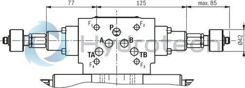
|
Mounting options: |
||||
|
Monitored spool position |
Ordering code |
Position switch on side |
||
|
„a“ |
„b“ |
"a" and "b" |
||
|
„a“ |
QMAG24 |
X |
||
|
„b“ |
QMBG24 |
X |
||
|
"a" and "b" |
QMABG24 |
X |
||
Mating connectors for valves with connector “K4”, without circuitry, standard
3P Z4
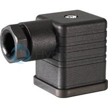
Mating connectors for valves with connector “K4”, without circuitry, standard
3P Z4
For valves with connector “K4” according to EN 175301-803 and ISO 4400, 2-pole + PE, “large cubic connector” Mating connectors for valves with one or two solenoids (individual connection)Data sheet
Spare parts & repair
Mating connectors for valves with connector “K4”, with indicator light
3P Z5L
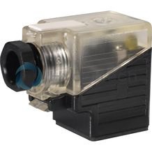
Mating connectors for valves with connector “K4”, with indicator light
3P Z5L
For valves with connector “K4” according to EN 175301-803 and ISO 4400, 2-pole + PE, “large cubic connector” Mating connectors for valves with one or two solenoids (individual connection)Data sheet
Spare parts & repair
Mating connectors for valves with connector “K4”, with indicator light and Zener diode suppression circuit
3P Z5L1
Mating connectors for valves with connector “K4”, with indicator light and Zener diode suppression circuit
3P Z5L1
For valves with connector “K4” according to EN 175301-803 and ISO 4400, 2-pole + PE, “large cubic connector” Mating connectors for valves with one or two solenoids (individual connection)Data sheet
Spare parts & repair
Mating connectors for valves with connector “K4”, with rectifier
3P RZ5
Mating connectors for valves with connector “K4”, with rectifier
3P RZ5
For valves with connector “K4” according to EN 175301-803 and ISO 4400, 2-pole + PE, “large cubic connector” Mating connectors for valves with one or two solenoids (individual connection)Data sheet
Spare parts & repair