

BOSCH REXROTH
R900588495
$22,664.88 USD
- BOSCH REXROTH
- Material:R900588495
- Model:DBGT-1X/400VE1
Quantity in stock: 0
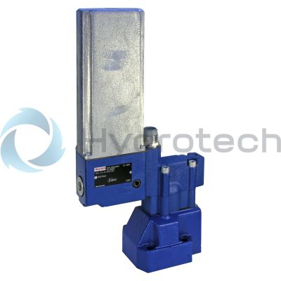
The Bosch Rexroth DBGT-1X/400VE1 (R900588495) is a high-performance industrial hydraulic valve designed for reliable pressure limitation and system pressure control. This pilot-operated pressure relief valve features a DC motor with speed reduction transmission for precise adjustment of system pressure. The motor adjusts the cam, which in turn tensions the spring to change the pressure. The main valve, with its spool insert, responds to variations in system pressure to maintain the set value. With a maximum operating pressure of 400 bar and a flow capacity that can handle significant volumes of hydraulic fluid, this valve is suitable for various demanding applications. It has a subplate mounting design conforming to ISO standards, ensuring compatibility with a wide range of systems. The DBGT-1X/400VE1 offers flexibility in actuation types, with options for electrical actuation using external electronics. For monitoring and feedback purposes, it comes equipped with an actual value potentiometer or optional limit switches that allow for minimum and maximum pressure limitations. In addition, it boasts self-locking capabilities in the event of power failure, ensuring maintained pressure settings. The valve is compatible with multiple types of hydraulic fluids including HL, HLP, HLPD, HVLP, HVLPD, HETG, HEES, HEPG, HFDU, and HFDR thanks to its FKM seals. Its robust construction and thoughtful design make it an essential component for various hydraulic systems requiring precise and reliable pressure control. Component series X ensures that users have access to the latest technological improvements and performance enhancements inherent in this series. The DBGT-1X/400VE1's integrated amplifier type VTVRM allows for program control and additional customization through supplementary pressure switches if needed. This makes the Bosch Rexroth DBGT-1X/400VE1 (R900588495) an adaptable solution for advanced industrial hydraulic applications requiring meticulous pressure management.
Size , X → Y, electrical with external amplifier,
Industrial hydraulic valve in a high performance range. Reliable limitation of the pressure to the command value signal.
Unpacked Weight: 5.4 kg
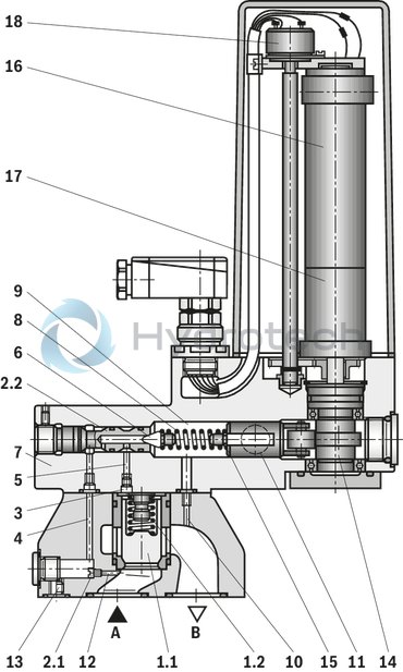
Pressure valves of type DBG are pilot-operated pressure relief valves. They are used for system pressure limitation. The pressure relief valves from this series mainly consist of a pilot control valve with electric motor as pressure adjustment element and main valve with main spool insert. The system pressure is set by means of a DC motor (16) with speed reduction transmission (17). The output shaft of the speed reduction transmission (17) turns the cam (14) that tensions the spring (8) via the spring plate (15) and thereby causes a pressure change. The pressure applied to channel A acts on the main spool (1.1). Simultaneously, pressure is applied to the spring-loaded side of the main spool (1.1) and to the pilot poppet (6) in the pilot control valve (7) via the control lines (4) and (5) which are equipped with nozzles (2.1, 2.2) and (3). If the system pressure exceeds the value set at the spring (8), the pilot poppet (6) opens. The signal for this is provided internally - with type DBG..–1X/.. via the control lines (12) and (4) from channel A; or externally – with type DBG..–1X/..X (XY) via the connection (13) and the control line (4). The pilot oil now flows via nozzle (2.1), control line (4), nozzle (2.2) and pilot poppet (6) into the spring chamber. From here, it is fed into the tank, either internally – with type DBG..–1X/.. via control line (10), or externally – with type DBG..–1X/..Y (XY) via control line (11). The compression spring (1.2) acts on the main spool (1.1) in closing direction, i. e. there is a pressure drop between side “A” and the spring-loaded side of the main spool (1.1). The flowing pilot oil volume is determined by the cross-section of the nozzles (2.1, 2.2) and by the pressure drop at the main spool (1.1). When the pressure in “A” has increased by the pressure drop at the main spool (1.1) in relation to the cracking pressure at the pilot poppet (6), the main spool (1.1) opens from “A” to “B”. The oil now flows from channel “A” to channel “B”, whilst the set operating pressure is maintained. The cam position (14) is reported back by the actual value potentiometer (18). Optionally, electric end switches can be installed instead of the actual value potentiometer (18) to limit the min. and max. pressure. For the version with limit switch, the min. adjustment time is 12 seconds for the pressure range pmin to pmax. The adjustment time of 12 seconds facilitates a sensitive start-up of the desired pressure in jog mode. For the version with actual value potentiometer, the min. adjustment time is 0.65 seconds for the pressure range pmin to pmax. The integrated amplifier type VT-VRM1-1 enables program control. With 2 additional pressure switches, the min. and max. pressure can be limited. If the energy supply is interrupted (cable break, fuse defect, short-circuit, etc.), the pressure adjusted at the valve remains unchanged for the version with limit switch.
| DC motor actuation |
| Pilot-operated |
| Pressure rating 400 bar |
| Proportional pressure valve in poppet seat design |
| Component series 1X |
| Operating pressure, max. 315 bar |
| Data Sheet | Download Data Sheet |
| Manual | Download Manual |
| Manual | Download Manual |
| Manual | Download Manual |
| Spool symbol | X → Y |
| Max. pressure | 315 |
| Electrical connection description | Mating connector 6-pole (5 + PE) according to DIN 43651 |
| Productgroup ID | 9,10,11,12,13,14 |
| Number of ports | 2 |
| Type of actuation | Electrical with external electronics |
| Electrical connector | Mating connector 6-pole (5 + PE) |
| Max. flow | 600 |
| Type of connection | Subplate mounting |
| Supply voltage | 24 VDC |
| Number of switching positions | 2 |
| Weight | 5.4 |
| Seals | FKM |
| Hydraulic fluid | HL,HLP,HLPD,HVLP,HVLPD,HETG,HEES,HEPG,HFDU,HFDR |
|
01 |
02 |
03 |
04 |
05 |
06 |
07 |
08 |
||
|
DBG |
T |
‒ |
1X |
/ |
* |
|
01 |
Pressure relief valve with DC motor actuation |
DBG |
|
02 |
separate pilot control valve asremote control valve (do not enter valve size) |
T |
|
03 |
Component series 10 ... 19 (10 ... 19: unchanged installation and connection dimensions) |
1X |
|
Pressure rating |
||
|
04 |
Set pressure up to 50 bar |
50 |
|
Set pressure up to 100 bar |
100 |
|
|
Set pressure up to 200 bar |
200 |
|
|
Set pressure up to 315 bar |
315 |
|
|
Set pressure up to 400 bar |
400 |
|
|
Pilot flow |
||
|
05 |
Pilot oil supply internal, pilot oil return internal |
no code |
|
External pilot oil supply, internal pilot oil return |
X |
|
|
Internal pilot oil supply, external pilot oil return |
Y |
|
|
External pilot oil supply, external pilot oil return |
XY |
|
|
Seal material |
||
|
06 |
NBR seals |
no code |
|
FKM seals |
V |
|
|
Observe compatibility of seals with hydraulic fluid used. (Other seals upon request) |
||
|
07 |
Limit switch |
E1 |
|
Actual value potentiometer |
P2 |
|
|
08 |
Further details in the plain text |
* |
For applications outside these parameters, please consult us!
general
|
Type |
DBGT | |
|
Size |
||
|
Component series |
1X | |
|
Installation position |
any | |
|
Earth |
kg |
5.1 |
|
Ambient temperature range |
°C |
-20 … +50 |
hydraulic
|
Maximum operating pressure |
bar |
315 | |
|
Port A |
bar |
315 | |
|
Port B (internal pilot oil return) |
bar |
10 | |
|
Port B (external pilot oil return) |
bar |
315 | |
|
Port X |
bar |
315 | |
|
Port Y |
bar |
10 | |
|
Maximum set pressure |
Pressure rating 50 bar |
bar |
50 |
|
Pressure rating 100 bar |
bar |
100 | |
|
Pressure rating 200 bar |
bar |
200 | |
|
Pressure rating 315 bar |
bar |
315 | |
|
Pressure rating 400 bar |
bar |
400 | |
|
Minimum set pressure |
qv dependent (see characteristic curves) | ||
|
Maximum flow |
l/min |
12 | |
|
Pilot flow |
l/min |
1 | |
|
Hydraulic fluid |
see table | ||
|
Hydraulic fluid temperature range |
°C |
-20 … +70 | |
|
Viscosity range |
mm²/s |
2.8 … 380 | |
|
Maximum admissible degree of contamination of the hydraulic fluid, cleanliness class according to ISO 4406 (c) 1) |
Class 20/18/15 according to ISO 4406 (c) | ||
| 1) | The cleanliness classes specified for the components must be adhered to in hydraulic systems. Effective filtration prevents faults and simultaneously increases the life cycle of the components. For the selection of the filters, see www.boschrexroth.com/filter. |
Hydraulic fluid |
Classification |
Suitable sealing materials |
Standards |
|
Mineral oils and related hydrocarbons |
HL, HLP |
NBR / FKM |
DIN 51524 |
|
Bio-degradable - insoluble in water |
HEES
|
FKM
|
VDMA24568
|
|
HETG
|
NBR / FKM |
||
|
HEPG
|
FKM
|
||
|
Important information on hydraulic fluids! Further information and information on the use of other hydraulic fluids on request! There may be limitations regarding the technical valve data (temperature, pressure range, life cycle, maintenance intervals, etc.)! The flash point of the process and operating medium used must be 40 K over the maximum solenoid surface temperature.Bio-degradable: When using bio-degradable hydraulic fluids that are zinc-solving, zinc may accumulate in the fluid (700mg zinc per pole tube) |
|||
electrical
|
Type |
DBGT | |
|
Voltage type |
Direct voltage | |
|
Power supply |
V |
24 |
|
Nominal power with limit switch |
W |
18 |
|
Nominal power with actual value potentiometer |
W |
24 |
|
Protection class according to DIN EN 60529 |
IP65 (with mating connector mounted and locked) | |
Control in jog mode with limit switch: Ordering code “E1”
|
Adjustment time, pmin ... pmax |
s |
12 |
|||||
|
Limit switch version: |
Microswitch |
30 V; 2 A DC |
|||||
|
electric load |
250 V; 5 A AC |
||||||
|
Pressure overrun: |
Pressure rating |
bar |
50 |
100 |
200 |
315 |
400 |
|
without short-circuit bridge |
bar |
1 |
2,5 |
5 |
7,5 |
10 |
|
|
with short-circuit bridge |
bar |
0,5 |
1 |
1,5 |
2 |
2,5 |
|
Adjustment with actual value potentiometer for cam position feedback: Ordering code “P2”
|
Adjustment time, pmin ... pmax |
s |
0,65 |
|||||
|
Potentiometer |
Resistance |
kΩ |
5 |
||||
|
Power |
W |
1,75 |
|||||
|
Adjustment hysteresis: breakout pressure - variation > 10 bar from nominal pressure |
|||||||
|
Pressure rating |
bar |
50 |
100 |
200 |
315 |
400 |
|
|
Hysteresis |
bar |
< 0,5 |
< 1 |
< 2,5 |
< 4 |
< 5 |
|
|
Adjustment hysteresis: breakout pressure - variation > 20 bar from nominal pressure |
|||||||
|
Pressure rating |
bar |
50 |
100 |
200 |
315 |
400 |
|
|
Hysteresis |
bar |
< 0,3 |
< 0,5 |
< 1 |
< 1,5 |
< 2 |
|
|
Repetition accuracy |
bar |
< 0,5 |
< 1 |
< 1,3 |
< 1,7 |
< 2 |
|
|
Valve amplifiers |
|||||||
|
Electric amplifier |
VT-VRM1-1-1X |
||||||
(measured at ν = 36 mm²/s and ϑOil = 50 °C)
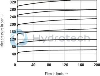
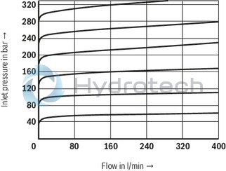
Inlet pressure dependent on the flow; NG10
Size 10
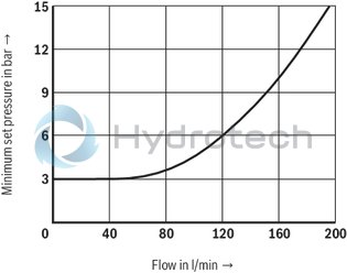
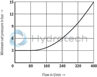
Minimum set pressure dependent on the flow; NG 10
Size 10
Inlet pressure dependent on the flow; NG25
NG25
Minimum set pressure dependent on the flow; NG 25
NG25
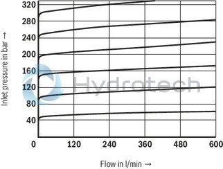
Inlet pressure dependent on the flow; NG32
Size 32
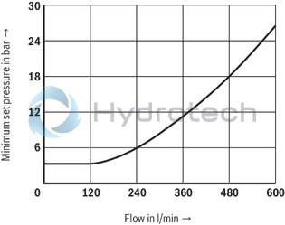
Minimum set pressure dependent on the flow; NG 32
Size 32
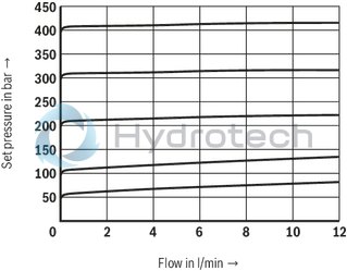
Set pressure dependent on the flow; pressure rating 400 bar
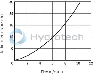
Minimum set pressure dependent on the flow; pressure rating 400 bar
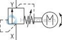
DBGC-1X/.. DBGT-1X/..
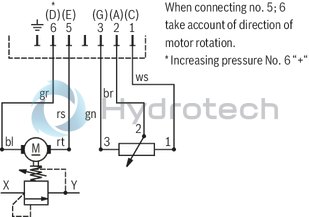
Connector connection at the DBG / DRG valve with actual value potentiometer
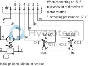
Connector connection at the DBG / DRG valve with end switch
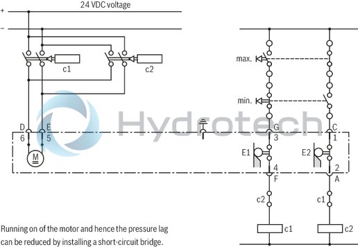
Switching example: DBG / DRG valve with end switch
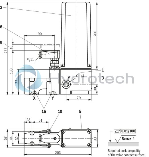
|
1 |
Pilot control valve |
|
2 |
DC motor |
|
3 |
“Y” port for “external” pilot oil return |
|
5 |
Name plate |
|
6 |
Mating connector |
|
9 |
Space required to remove the mating connector |
|
10 |
Valve mounting bores |
|
16 |
O-ring 9.25 x 1.78 |
Recommended valve mounting screws (separate order):
4 hexagon socket head cap screws ISO 4762 - M8 x 50 - 10.9-flZn-240h-L
Tightening torque MA = 31 Nm ± 10%; material no. R913000543