
BOSCH REXROTH
R900493939
$381.00 USD
- BOSCH REXROTH
- Material:R900493939
- Model:DB20K2-1X/315XY
Quantity in stock: 0
The Bosch Rexroth DB 20 K2-1X/315XY (R900493939) is a highly versatile, pilot-operated pressure relief valve designed for controlling operating pressure within hydraulic systems. This screw-in cartridge valve can handle a maximum operating pressure of up to 315 bar and allows for a maximum flow of 20 liters per minute. It features an Mx cavity and utilizes NBR sealing material to ensure reliable performance under various operating conditions. The DB 20 K2-1X/315XY is equipped with a poppet type spool that ensures stable operation and precise control over the hydraulic fluid flow from channel P to channel T. The valve's design includes a housing and a pilot control valve with multiple adjustment options, such as a sleeve with hexagon and protective cap, allowing for easy customization according to specific application requirements. This model is part of the DB.K product family, known for its robustness in piloted pressure relief applications. The external pilot oil supply and return ensure effective functioning of the main spool, while the internal version allows for seamless integration into various hydraulic circuits. Additionally, it comes with port X which can be used to unload the valve or switch it to another pressure setting if required. The DB 20 K2-1X/315XY offers different mounting options including subplate mounting compatible with ISO NG6 and ISO NG10 standards. Users can select from four distinct adjustment types for pressure settings: rotary knob, sleeve with hexagon and protective cap, lockable rotary knob with scale, or rotary knob with scale. The valve also provides size component series X specifications ensuring compatibility across diverse hydraulic systems. Overall, the Bosch Rexroth DB 20 K2-1X/315XY stands out as an efficient solution for limiting operating pressures in hydraulic systems while offering ease of maintenance and adaptability across various industrial applications.
Pressure relief valve, pilot operated
Unpacked Weight: 0.3191 kg
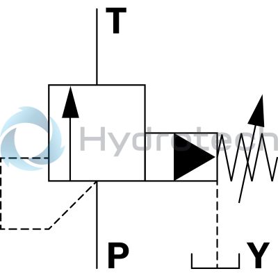
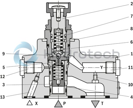
Valves of type DB are pilot-operated pressure relief valves. They are used for limitation of the operating pressure.
The valves basically consist of housing (1) and pilot control valve (2) with adjustment type.
The pressure applied to channel P acts on the main spool (3). Via the nozzle bores (4 and 5), the pressure is at the same time applied to poppet (6). If the pressure in channel P exceeds the value set at spring (7), poppet (6) opens against spring (7). Via the nozzle bores (4 and 5), the hydraulic fluid from channel P now flows into the spring chamber (8). From here, it is led into the tank internally (version "–"), via the control line (9 and 10), or externally (version "Y") via the control line (9 and 11).
Due to the state of equilibrium at the main spool (3), hydraulic fluid flows from channel P to channel T, maintaining the set operating pressure.
A pressure gauge connection (12) allows for the control of the operating pressure.
The pressure relief valve can be unloaded or switched to another pressure (second pressure rating) via port X (13).
| Screw-in cartridge valve |
| Maximum operating pressure 350 bar (5000 psi) |
| Maximum flow 400 l/min (106 gpm) |
| Cavity M28x1,5 |
| Data Sheet | Download Data Sheet |
| Max. pressure | 350 |
| Adjustment options | Sleeve with hexagon and protective cap |
| Product family classification | Pressure relief valve, pilot operated |
| Productgroup ID | 9,10,11,12,13,14 |
| Product family type | DB.K |
| Ports number | 4 |
| Type of actuation | with manual actuation |
| Sealing material | NBR |
| Cavity | M28x1,5 |
| Product type | DB.K |
| Max. flow | 400 |
| Type of connection | Screw-in cartridge valve |
| Nominal flow | 400 |
| Direct - Pilot | Pilot operated |
| Product family | Relief |
| Pilot oil supply and return | External pilot oil supply and pilot oil return |
| Spool Poppet | Poppet type |
| Weight | 0.3191 |
| Hydraulic fluid | HL,HLP,HLPD,HVLP,HVLPD,HFC |
|
01 |
02 |
03 |
04 |
05 |
06 |
07 |
08 |
09 |
10 |
11 |
12 |
||
|
DB |
– |
4X |
/ |
W65 |
* |
|
Type |
||
|
01 |
Pressure relief valve |
DB |
|
02 |
Without directional valve |
no code |
|
Size |
||
|
03 |
Size 10 |
|
|
Subplate mounting "–" |
10 |
|
|
Threaded connection "G" (G1 1/2) |
10 |
|
|
Size 25 |
||
|
Subplate mounting "–" |
20 |
|
|
Threaded connection "G" (G3/4) |
15 |
|
|
Threaded connection "G" (G1) |
20 |
|
|
Type of connection |
||
|
04 |
Subplate mounting |
– |
|
Threaded connection |
G |
|
|
Adjustment type |
||
|
05 |
Rotary knob |
1 |
|
Sleeve with hexagon and protective cap |
2 |
|
|
Lockable rotary knob with scale |
3 1) |
|
|
Rotary knob with scale |
7 |
|
|
Component series |
||
|
06 |
Component series 40 ... 49 (40 ... 49: unchanged installation and connection dimensions) |
4X |
|
Pressure rating |
||
|
07 |
Set pressure up to 50 bar |
50 |
|
Set pressure up to 100 bar |
100 |
|
|
Set pressure up to 200 bar |
200 |
|
|
Set pressure up to 315 bar |
315 |
|
|
Set pressure up to 350 bar |
350 |
|
|
Pilot oil supply and pilot oil return (see also Symbols) |
||
|
08 |
External pilot oil supply, internal pilot oil return |
X |
|
Internal pilot oil supply, external pilot oil return |
Y |
|
|
Pilot oil supply and pilot oil return external |
XY |
|
|
Version |
||
|
09 |
Standard version |
no code |
|
Valve for minimum cracking pressure (not suitable for mutual relief!) |
U |
|
|
Seal material |
||
|
10 |
NBR seals |
no code |
|
FKM seals |
V |
|
|
(other seals upon request) Attention! Observe compatibility of seals with hydraulic fluid used! |
||
|
Installation position |
||
|
11 |
Vertical installation position of the screw-in cartridge valve (cartridge) |
W65 |
|
12 |
Further details in the plain text |
* |
| 1) H-key with material no. R900008158 is included in the scope of delivery. |
Notice:
Preferred types and standard units are contained in the EPS (standard price list).
general
|
Size |
10 | 25 | ||
|
Weight |
Subplate mounting "–" |
kg |
1.6 | 2.3 |
|
Threaded connection "G" |
kg |
2.95 | ||
|
Installation position |
any | |||
|
Ambient temperature range |
NBR seals |
°C |
-30 … +80 | |
|
FKM seals |
°C |
-15 … +80 | ||
|
Minimum stability of the housing materials |
Housing materials are to be selected so that there is sufficient safety for all imaginable operating conditions (e.g. with regard to pressure resistance, thread stripping strengths and tightening torques). | |||
hydraulic
|
Size |
10 | 25 | |||
|
Maximum operating pressure |
Port P |
bar |
350 | ||
|
Port X |
bar |
350 | |||
|
Port T |
bar |
315 | |||
|
Maximum counter pressure |
Port Y |
bar |
250 | ||
|
Minimum set pressure |
flow-dependent, see characteristic curves | ||||
|
Maximum set pressure |
bar |
50 100 200 315 350 |
|||
|
Maximum flow |
Subplate mounting "–" |
l/min |
200 | 400 | |
| G3/4 | G1 | ||||
|
Threaded connection "G" |
l/min |
150 | 200 | 300 | |
|
Hydraulic fluid |
see table below | ||||
|
Hydraulic fluid temperature range |
NBR seals |
°C |
-20 … +80 | ||
|
FKM seals |
°C |
-15 … +80 | |||
|
Viscosity range |
mm²/s |
10 … 800 | |||
|
Maximum admissible degree of contamination of the hydraulic fluid 1) |
Class 20/18/15 according to ISO 4406 (c) | ||||
| 1) | The cleanliness classes specified for the components must be adhered to in hydraulic systems. Effective filtration prevents faults and simultaneously increases the life cycle of the components. For the selection of the filters, see www.boschrexroth.com/filter. |
|
Hydraulic fluid |
Classification |
Suitable sealing materials |
Standards |
Data sheet |
|
|
Mineral oils |
HL, HLP |
NBR, FKM |
DIN 51524 |
90220 |
|
|
Bio-degradable |
Insoluble in water |
HETG |
FKM |
ISO 15380 |
90221 |
|
HEES |
FKM |
||||
|
Soluble in water |
HEPG |
FKM |
ISO 15380 |
90221 |
|
|
Important information on hydraulic fluids: For further information and data on the use of other hydraulic fluids, please refer to the data sheets above or contact us. There may be limitations regarding the technical valve data (temperature, pressure range, life cycle, maintenance intervals, etc.). The ignition temperature of the hydraulic fluid used must be 50 K higher than the maximum surface temperature.Bio-degradable: If this hydraulic fluid is used, small amounts of dissolved zinc may get into the hydraulic system. |
|||||
For applications outside these parameters, please consult us!
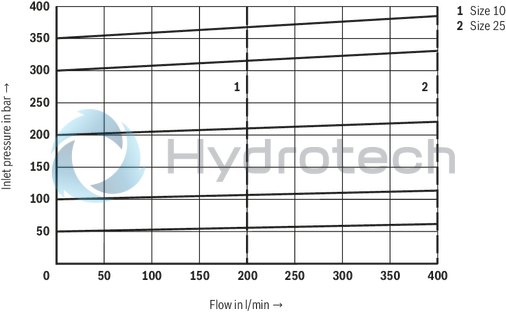
(measured with HLP46, ϑOil = 40 ±5 °C)
Inlet pressure dependent on the flow
Subplate mounting
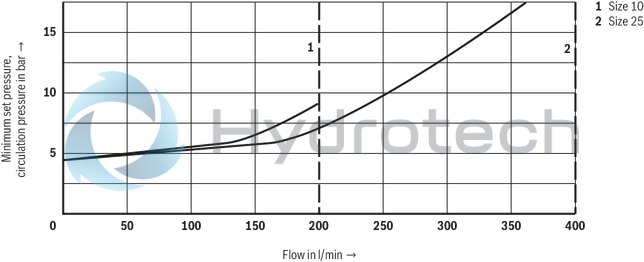
Minimum set pressure and circulation pressure dependent on the flow 1)
Standard version
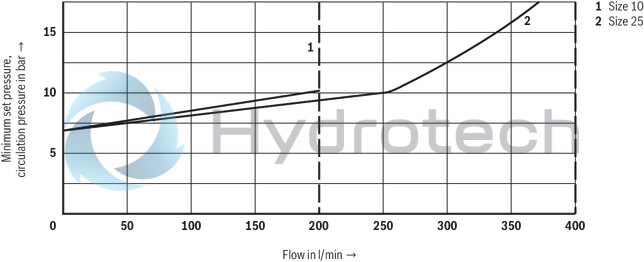
| 1) | The characteristic curves apply to the pressure at the valve output pT = 0 bar across the entire flow range. |
Minimum set pressure and circulation pressure dependent on the flow 1)
Version “U”
| 1) | The characteristic curves apply to the pressure at the valve output pT = 0 bar across the entire flow range. |
Threaded connection
Minimum set pressure and circulation pressure dependent on the flow 1)
Standard version
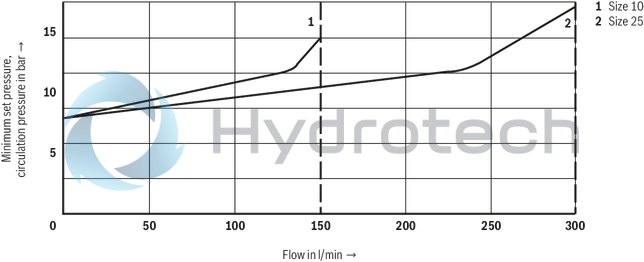
| 1) | The characteristic curves apply to the pressure at the valve output pT = 0 bar across the entire flow range. |
Minimum set pressure and circulation pressure dependent on the flow 1)
Version “U”
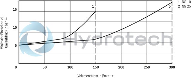
| 1) | The characteristic curves apply to the pressure at the valve output pT = 0 bar across the entire flow range. |
Notices:
The characteristic curves were measured with external, depressurized pilot oil return.
Due to the internal pilot oil return, the inlet pressure increases by the output pressure present in port T.
Type DB…–…

Type DB…X…

Type DB…Y…

Type DB…XY…

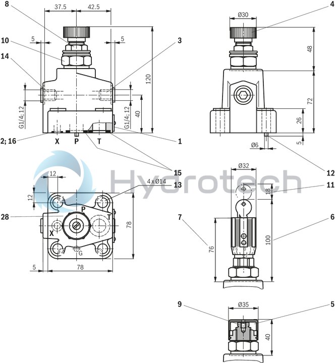
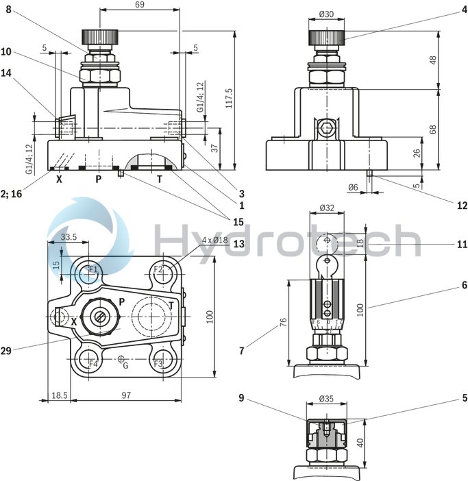
Subplate mounting
Size 10
Dimensions in mm
|
|
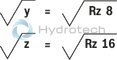
Required surface quality of the valve contact surface |
|
1 |
Name plate |
|
2 |
Port X for remote control, optional |
|
3 |
Y port for pilot oil return, external |
|
4 |
Adjustment type "1" |
|
5 |
Adjustment type "2" |
|
6 |
Adjustment type "3" |
|
7 |
Adjustment type "7" |
|
8 |
Lock nut SW22, tightening torque MA = 10±5 Nm |
|
9 |
Hexagon SW10 |
|
10 |
Hexagon SW30, tightening torque MA = 50 Nm |
|
11 |
Space required to remove the key |
|
12 |
Locating pin |
|
13 |
Valve mounting bores |
|
14 |
Pressure gauge connection |
|
15 |
Identical seal rings for ports P and T |
|
16 |
Seal ring for port X |
|
28 |
Porting pattern according to ISO 6264-06-09-*-97 |
Valve mounting screws (separate order)
For reasons of stability, exclusively the following valve mounting screws may be used:
4 x ISO 4762 - M12 x 50 - 10.9-flZn-240h-L
with friction coefficient μtotal = 0.09 … 0.14,
tightening torque MA = 75 Nm ± 10 %,
material no. R913000283
Notice:
The tightening torques are guidelines when using screws with the specified friction coefficients and when using a manual torque wrench (tolerance ± 10 %).
Subplates (separate order) with porting pattern according to ISO 6264-06-09-*-97 see data sheet 45100.
NG25
Dimensions in mm
|
|
|
Required surface quality of the valve contact surface |
|
1 |
Name plate |
|
2 |
Port X for remote control, optional |
|
3 |
Y port for pilot oil return, external |
|
4 |
Adjustment type "1" |
|
5 |
Adjustment type "2" |
|
6 |
Adjustment type "3" |
|
7 |
Adjustment type "7" |
|
8 |
Lock nut SW22, tightening torque MA = 10±5 Nm |
|
9 |
Hexagon SW10 |
|
10 |
Hexagon SW30, tightening torque for screw-in MA = 50 Nm |
|
11 |
Space required to remove the key |
|
12 |
Locating pin |
|
13 |
Valve mounting bores |
|
14 |
Pressure gauge connection |
|
15 |
Identical seal rings for ports P and T |
|
16 |
Seal ring for port X |
|
29 |
Porting pattern according to ISO 6264-08-13-*-97 |
Valve mounting screws (separate order)
For reasons of stability, exclusively the following valve mounting screws may be used:
4 x ISO 4762 - M16 x 50 - 10.9-flZn-240h-L
with friction coefficient μtotal = 0.09 … 0.14,
tightening torque MA = 185 Nm ± 10 %,
material no. R913000378
Notice:
The tightening torques are guidelines when using screws with the specified friction coefficients and when using a manual torque wrench (tolerance ± 10 %).
Subplates (separate order) with porting pattern according to ISO 6264-08-13-*-97, see data sheet 45100.
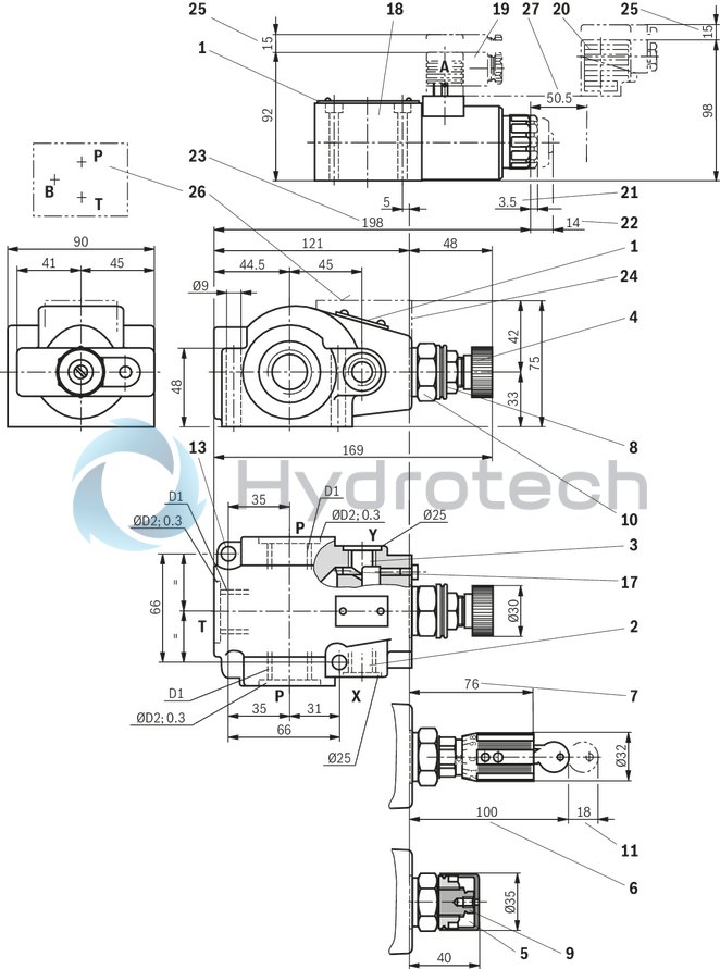
Threaded connection
Dimensions in mm
|
1 |
Name plate |
|
2 |
Port X for remote control, optional |
|
3 |
Y port for pilot oil return, external |
|
4 |
Adjustment type "1" |
|
5 |
Adjustment type "2" |
|
6 |
Adjustment type "3" |
|
7 |
Adjustment type "7" |
|
8 |
Lock nut SW22, tightening torque MA = 10±5 Nm |
|
9 |
Hexagon SW10 |
|
10 |
Hexagon SW30, tightening torque MA = 50 Nm |
|
11 |
Space required to remove the key |
|
17 |
Grub screw is omitted with internal pilot oil return |
|
18 |
Directional spool valve NG6 (data sheet 23178) |
|
19 |
Mating connector without circuitry (separate order) |
|
20 |
Mating connector with circuitry (separate order) |
|
21 |
Dimension for valve without manual override |
|
22 |
Dimension for valve with manual override "N" |
|
23 |
Dimension for valve with concealed manual override "N9" |
|
24 |
Housing for version "W“ |
|
25 |
Space required to remove the mating connector |
|
26 |
Valve contact surface; port A is not bored |
|
27 |
Space required to remove the solenoid coil |
|
Version |
D1 |
ØD2 |
|
mm |
||
| DB.10.G | G1/2 | 34 |
| DB.15.G | G3/4 | 42 |
| DB.20.G | G1 | 47 |
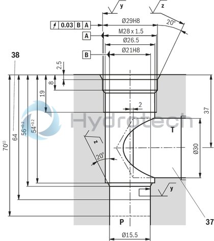
Mounting cavity
Version "XY" and type-examination tested safety valves version "Y…E"
Dimensions in mm
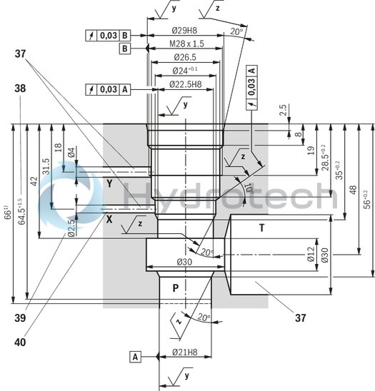
| 1) | Installation depth |
|
|
Required surface quality of the valve contact surface |
|
37 |
Bore X, Y and T optionally at the circumference for version "XY" Bore T optionally at the circumference for version "Y" (no separate bore Y required; pilot oil return via bore T) |
|
38 |
Depth of fit |
|
39 |
Bore Ø2.5 mm is only to be bored if required |
|
40 |
Port X does not have to be bored for type-examination tested safety valves version "Y…E" as it does not have any function! |
Version “Y”
Dimensions in mm
| 1) | Installation depth |
|
|
|
Required surface quality of the valve contact surface |
|
37 |
Bore X, Y and T optionally at the circumference for version "XY" Bore T optionally at the circumference for version "Y" (no separate bore Y required; pilot oil return via bore T) |
|
38 |
Depth of fit |
The unloading function (directional valve function with version "W") must not be used for safety functions! Hydraulic counter pressures in port T with internal pilot oil return and/or port Y with external pilot oil return add 1:1 to the response pressure of the valve set at the pilot control.
Example:
Pressure adjustment of the valve due to spring preloading (item 7 see product description) in the pilot control valve/adjustment type
pSpring = 200 bar
Hydraulic counter pressure in port T with internal pilot oil return phydraulic = 50 bar
=> response pressure = pSpring + phydraulic = 250 bar
Mating connectors for valves with connector “K4”, without circuitry, standard
3P Z4
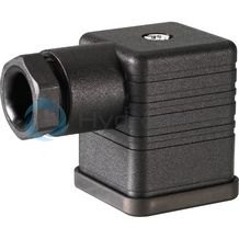
Mating connectors for valves with connector “K4”, without circuitry, standard
3P Z4
For valves with connector “K4” according to EN 175301-803 and ISO 4400, 2-pole + PE, “large cubic connector” Mating connectors for valves with one or two solenoids (individual connection)Data sheet
Spare parts & repair
Mating connectors for valves with connector “K4”, with indicator light
3P Z5L
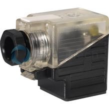
Mating connectors for valves with connector “K4”, with indicator light
3P Z5L
For valves with connector “K4” according to EN 175301-803 and ISO 4400, 2-pole + PE, “large cubic connector” Mating connectors for valves with one or two solenoids (individual connection)Data sheet
Spare parts & repair
Mating connectors for valves with connector “K4”, with indicator light and Zener diode suppression circuit
3P Z5L1
Mating connectors for valves with connector “K4”, with indicator light and Zener diode suppression circuit
3P Z5L1
For valves with connector “K4” according to EN 175301-803 and ISO 4400, 2-pole + PE, “large cubic connector” Mating connectors for valves with one or two solenoids (individual connection)Data sheet
Spare parts & repair
Mating connectors for valves with connector “K4”, with rectifier
3P RZ5
Mating connectors for valves with connector “K4”, with rectifier
3P RZ5
For valves with connector “K4” according to EN 175301-803 and ISO 4400, 2-pole + PE, “large cubic connector” Mating connectors for valves with one or two solenoids (individual connection)Data sheet
Spare parts & repair