


BOSCH REXROTH
R201081314
$308.72 USD
- BOSCH REXROTH
- Material:R201081314
- Model:KWD-020-SKS-C1-H-0
Quantity in stock: 0
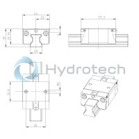
The Bosch Rexroth B.RUN. BLOCK NRFG KWD-020-SKS-C1-H-0 (R201081314) is a high-precision ball runner block designed for use in environments where corrosion resistance and precision are paramount, such as the packaging and food industry subsectors. With size specifications that include a slimline width, short length, and standard height, this model boasts a body made of corrosion-resistant steel compliant with DIN standards. It features a low preload class C and high accuracy class H, ensuring reliable performance with minimized elastic deflection variation due to its optimized entry-zone geometry and numerous balls. This ball runner block is distinctive for its lack of a ball chain, preservation, initial lubrication, and attachment elements on both the left and right front reference edges. It comes with a straight lube connection that is loosely attached. The runner block has an overall length of 63 mm and offers interchangeability across all SNS ball guide rails within each accuracy class due to its consistent dimensional tolerance. Designed for long-term use, it allows for lubrication over several years while maintaining maximum system rigidity through its preloaded O-arrangement. This rigidity extends to all load directions, which can facilitate applications that require only one runner block per rail. The product includes an end-face fastening thread for various attachments and features integrated all-around sealing to protect against contaminants. The B.RUN. BLOCK NRFG KWD-020-SKS-C1-H-0 operates smoothly and quietly thanks to its well-designed ball return system and guidance mechanism. Attachments can be mounted from above the block for ease of assembly. Its dynamic characteristics are excellent with high load ratings possible in all four main loading directions, underscoring its versatility across various applications without sacrificing performance or longevity.
NRFG ball runner block, SKS, size 20, Resist NR, accuracy high, low preload
The high-precision ball runner block made of Resist NR is suitable for use in the packing industry and in food industry sub-sectors. Additionally, it is characterized by the following product features:
Size 20
Format SKS: Width = slimline, length = short, height = standard
Runner block body and all steel components made of corrosion-resistant steel as per DIN 10088
Preload class C1: Low preload
Accuracy class H: High
Without ball chain
Without preservation
Without initial lubrication
Without attachment element, left (front reference edge)
Without attachment element, right (front reference edge)
Straight lube connection loosely attached.
Runner block body in standard version
Overall length of the runner block = 57.3 mm
Interchangeability: The runner block and the guide rails can be combined with each other with every accuracy.
Unpacked Weight: 0.25 kg
Material specifications
| All metal parts are made of corrosion resistant steel |
| All plastic parts are made from certified materials |
| Excellent dynamic characteristics: Excellent dynamic characteristics |
| The same high load ratings in all four main directions of loading |
| Can be used on all SNS ball guide rails |
| Long-term lubrication is possible over several years |
| Lube fittings with metal threads on all sides |
| Limitless interchangeability as all ball guide rail systems can be combined at will with all ball runner block versions within each accuracy class. |
| Maximum system rigidity due to preloaded O-arrangement |
| End-face fastening thread for all attachments |
| High rigidity in all load directions – permits applications with just one runner block per rail |
| Integrated all-round sealing |
| Optimized entry-zone geometry and high number of balls minimize variation in elastic deflection |
| Smooth, quiet running thanks to optimally designed ball return and guideway |
| Attachments on the ball runner block can be mounted from above |
| Data Sheet | Download Data Sheet |
| 3D CAD | Download 3D CAD |
| Manual | Download Manual |
| Manual | Download Manual |
| Manual | Download Manual |
| Manual | Download Manual |
| Material (profiled rail systems) | Corrosion resistant steel |
| Size N6 with tolerance (profiled rail systems) | 13,2 mm ±0,5 |
| Height of runner block | 25.35 |
| Footnote dynamic load capacity C | Determination of the dynamic load capacities and load moments is based on a 100 000 m travel as per DIN ISO 14728-1. Often only 50 000 m are actually stipulated. For comparison: Multiply values C, Mt and ML from the table by 1.26. |
| Size S5 (profiled rail system) | 6 |
| Max. acceleration amax | 500 |
| Permissible ambient temperature | -10 °C ... +80 °C |
| Size A (profiled rail systems) | 44 |
| Size N6 tolerance (profiled rail systems) | |
| Size A3 (profiled rail systems) | 12 |
| Preload force | 160 |
| Format | SKS - slimline, short, standard height |
| Size A2 (profiled rail systems) | 20 |
| Self-aligning for compensation of misalignments | Without self-alignment |
| Maximum permissible linear speed vmax | 5 |
| Lubrication | Without initial lubrication and without preservation |
| Ball chain | Without ball chain (standard) |
| Size N3 (profiled rail systems) | 7.5 |
| Pitch T guide rail | 60 |
| Height of runner block with guide rail | 30 |
| Static load rating C0 | 9400 |
| Dynamic torsional moment load capacity Mt | 125 |
| Size N6 (profiled rail systems) | 13.2 |
| Size H2 with cover strip (profiled rail systems) | 20.55 |
| Size B (profiled rail systems) | 57.3 |
| Preload class | C1 - Low preload |
| Size H2 with cover strip (profiled rail systems) | 20.75 |
| Seal | SS – Standard seal |
| Size B1 (profiled rail systems) | 31.9 |
| Size H (profiled rail system) | 30 |
| Size K2 (profiled rail systems) | 22.95 |
| Size V1 | 6 |
| Height of guide rail H2 with cover strip | 20.75 |
| Productgroup ID | 17 |
| Accuracy class | H - Highly accurate |
| Size K4 (profiled rail systems) | 3.35 |
| Size B with tolerance (profiled rail systems) | 57,3 mm |
| Size K1 (profiled rail systems) | 22.95 |
| Size K3 (profiled rail systems) | 3.35 |
| Size A1 (profiled rail systems) | 22 |
| Dynamic longitudinal moment load capacity ML footnote | Determination of the dynamic load capacities and load moments is based on a 100 000 m travel as per DIN ISO 14728-1. Often only 50 000 m are actually stipulated. For comparison: Multiply values C, Mt and ML from the table by 1.26. |
| Size S9 thread diameter x lead with tolerance (profiled rail systems) | M3x5 |
| Dynamic longitudinal moment load capacity ML | 45 |
| Size S2 (profiled rail systems) | M5 |
| Static torsional moment load capacity Mt0 | 115 |
| Note: Max. acceleration amax | If Fcomb◡> 2.8 • Fpr : amax = 50 m/s2 |
| Runner block or guide rail | Runner block |
| Width of runner block | 44 |
| Size T1 min (profiled rail systems) | 13 |
| Dynamic torsional moment load capacity Mt footnote | Determination of the dynamic load capacities and load moments is based on a 100 000 m travel as per DIN ISO 14728-1. Often only 50 000 m are actually stipulated. For comparison: Multiply values C, Mt and ML from the table by 1.26. |
| Size E8 (profiled rail systems) | 32.5 |
| Length of runner block | 57.3 |
| Size S9 thread diameter x lead with (profiled rail systems) | M3x5 |
| Linear guide type | Ball rail system |
| Dynamic load capacity C | 8200 |
| Static longitudinal moment load capacity ML0 | 40 |
| Size E9 (profiled rail systems) | 7.3 |
| Size E1 (profiled rail systems) | 32 |
| Weight | 0.25 |
| Nominal size | 20 |
| Size H1 (profiled rail systems) | 25.35 |

Load capacities and load moments
|
Size |
15 | 20 | 25 | 30 | 35 | ||
|
C |
N |

|
4500 | 8200 | 10500 | 14500 | 19300 |
|
C0 |
N |
5600 | 9400 | 12600 | 17200 | 22400 | |
|
Mt |
Nm |

|
44 | 125 | 195 | 320 | 545 |
|
Mt0 |
Nm |
55 | 115 | 180 | 295 | 485 | |
|
ML |
Nm |
|
16 | 45 | 70 | 110 | 170 |
|
ML0 |
Nm |
19 | 40 | 65 | 105 | 150 | |
| The calculation of the dynamic load ratings and load moments is based on a stroke length of 100,000 m as per DIN ISO 14728-1. However, often only 50,000 m is actually stipulated. For comparison: Multiply the values C,Mt and ML from the table by 1.26. |
General technical data
|
Size |
15 | 20 | 25 | 30 | 35 | |
|
amax 1) |
m/s² |
500 | ||||
|
vmax |
m/s |
5 | ||||
|
m |
kg |
0.1 | 0.25 | 0.35 | 0.6 | 0.9 |
| 1) | If Fcomb > 2.8 • Fpr : amax = 50 m/s2 |
Legend
|
Symbol |
Description |
Unit |
|
amax |
Maximum acceleration travel |
m/s2 |
|
C |
Dynamic load capacity |
N |
|
C0 |
Static load capacity |
N |
|
m |
Mass |
kg |
|
ML |
Dynamic longitudinal moment load capacity |
Nm |
|
ML0 |
Static longitudinal moment load capacity |
Nm |
|
Mt |
Dynamic torsional moment load capacity |
Nm |
|
Mt0 |
Static torsional moment laod capacity |
Nm |
|
vmax |
Maximum permissible speed |
m/s |
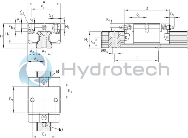
| a) | For O-ring |
| Size 15: Ø 4 · 1.0 (mm) | |
| Sizes 20 - 35: Ø 5 · 1.0 (mm) | |
| Open the lube port if required | |
| b) | Lube nipple, sizes 15 – 20: |
| Funnel-type lube nipple DIN 3405-A M3x5, B2 = 1.6 mm | |
| If you use different lube nipples, observe the screw-in depth of 5 mm! | |
| Lube nipple, sizes 25 - 35: | |
| Hydraulic-type lube nipple DIN 71412-A M6x8, B2 = 9.5 mm | |
| If you use different lube nipples, observe the screw-in depth of 8 mm! | |
| The lube nipple is included in the scope of delivery (not installed). | |
| Connection possible on all sides. |
Dimensions
|
Size |
15 | 20 | 25 | 30 | 35 | |
|
A |
mm |
34 | 44 | 48 | 60 | 70 |
|
A1 |
mm |
17 | 22 | 24 | 30 | 35 |
|
A2 |
mm |
15 | 20 | 23 | 28 | 34 |
|
A3 |
mm |
9.5 | 12 | 12.5 | 16 | 18 |
|
B |
44.7 mm | 57.3 mm | 67 mm | 75.3 mm | 84.9 mm | |
|
B1 |
mm |
25.7 | 31.9 | 38.6 | 45 | 51.4 |
|
E1 |
mm |
26 | 32 | 35 | 40 | 50 |
|
E8 |
mm |
24.55 | 32.5 | 38.3 | 48.4 | 58 |
|
E9 |
mm |
6.7 | 7.3 | 11.5 | 14.6 | 17.35 |
|
H |
mm |
24 | 30 | 36 | 42 | 48 |
|
H1 |
mm |
19.9 | 25.35 | 29.9 | 35.35 | 40.4 |
|
Dimension H2 with cover strip |
mm |
16.3 | 20.75 | 24.45 | 28.55 | 32.15 |
|
Dimension H2 without cover strip |
mm |
16.2 | 20.55 | 24.25 | 28.35 | 31.85 |
|
K1 |
mm |
16.25 | 22.95 | 25.35 | 28.8 | 32.7 |
|
K2 |
mm |
17.85 | 22.95 | 26.5 | 30.5 | 34.2 |
|
K3 |
mm |
3.2 | 3.35 | 5.5 | 6.05 | 6.9 |
|
K4 |
mm |
3.2 | 3.35 | 5.5 | 6.05 | 6.9 |
|
N3 |
mm |
6 | 7.5 | 9 | 12 | 13 |
|
N6 |
10.3 mm ±0.5 | 13.2 mm ±0.5 | 15.2 mm ±0.5 | 17 mm ±0.5 | 20.5 mm ±0.5 | |
|
S2 |
M4 | M5 | M6 | M8 | ||
|
ØS5 |
4.5 | 6 | 7 | 9 | ||
|
S9 |
M2.5x3.5 | M3x5 | ||||
|
T |
mm |
60 | 80 | |||
|
V1 |
mm |
5 | 6 | 7.5 | 7 | 8 |
Combinations of different accuracy classes
Combining Ball Guide Rails and Ball Runner Blocks of different accuracy classes results in different tolerances for the dimensions H and A3. See "Accuracy classes and their tolerances” in the Ball Rail Systems
Hygienic design
Product requirements for specific areas
Notes on using the Ball Rail Systems NRFG
For further information, additional technical data and maintenance notes, see the Ball Rail System.