BOSCH REXROTH
R190415210
$219.22 USD
- BOSCH REXROTH
- Material:R190415210
- Model:DOUBLE CAM BEARING LWA-052-SNS-FN-E-0
Quantity in stock: 0
The Bosch Rexroth DOUBLE CAM BEARING LWA-052-SNS-FN-E-0 (R190415210) is a high-precision linear motion component designed for seamless integration into handling and automation technology applications. This cam roller double bearing boasts an economic accuracy class E, indicating a balance between performance and cost-effectiveness. The runner block body is constructed from aluminum, ensuring a lightweight yet sturdy design suitable for standard load applications. This model features a slimline width in the SNS format with standard height and length dimensions, allowing for versatile installation in various machine configurations. The absence of preservation, initial lubrication, and attachment elements on both the left front and right front reference edges simplifies the setup while providing flexibility for custom installations. Integrated lube nipples facilitate maintenance by allowing for straightforward grease lubrication, which is recommended to ensure optimal performance. The DOUBLE CAM BEARING LWA-052-SNS-FN-E-0 offers zero-clearance adjustment through socket hex screws located on the rear side of the runner blocks, contributing to precision alignment and smooth operation. It includes a robust all-around sealing system with excellent wiping action to protect against contaminants. The product's dynamic load capacities in both y-direction (Cy) and z-direction (Cz), along with its maximum static loads (Fy max and Fz max), cater to various operational demands. Built to accommodate a wide range of operating temperatures from -20°C to +80°C, this cam roller guide can withstand diverse environmental conditions. It also features impressive torsional moment capacities around all axes (Mx, My, Mz), ensuring stability under dynamic loads. Overall, the Bosch Rexroth DOUBLE CAM BEARING LWA-052-SNS-FN-E-0 represents a reliable solution for linear motion requirements in automation tasks where precision and durability are paramount. Its combination of economic accuracy with robust construction makes it an ideal choice for engineers looking to optimize their systems' efficiency without compromising on quality or performance.
The cam roller double bearing is characterized by the following product features: Format SNS, size 52, aluminum, accuracy economic, load class FN
The cam roller double bearing is characterized by the following product features:
Size 52
Format SNS: Width = slimline, length = normal, height = standard
Runner block body made of aluminum
Standard load carrying capacity
Accuracy class E: Economic
Without preservation
Without initial lubrication
Without attachment element, left (front reference edge)
Without attachment element, right (front reference edge)
Lube nipple integrated
Standard version
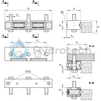
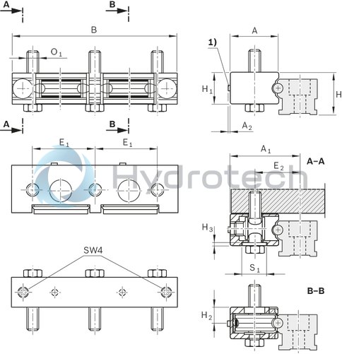
Overall length of the runner block = 159
Interchangeable element
Unpacked Weight: 0.571 kg
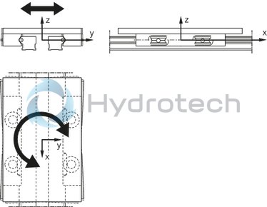
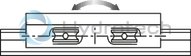
Rexroth cam roller guides were specially developed for handling and automation technology.
Product overview
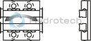
| Distance of the runner blocks on the table construction is freely selectable |
| Zero-clearance adjustment using socket hex screws on the rear side of the runner blocks. |
| Tough all-round sealing with excellent wiping action. Grease lubrication recommended. |
| On two half-rails |
| Data Sheet | Download Data Sheet |
| 2D CAD | Download 2D CAD |
| 2D CAD | Download 2D CAD |
| 3D CAD | Download 3D CAD |
| 3D CAD | Download 3D CAD |
| Manual | Download Manual |
| Manual | Download Manual |
| Manual | Download Manual |
| Manual | Download Manual |
| Manual | Download Manual |
| Maximum static load due to a resulting force in the y-direction F0y max | 2500 |
| Height of runner block | 29.5 |
| Dynamic load capacity in z-direction Cz | 10050 |
| Maximum operating temperature | |
| Static load capacity in z-direction C0z | 4900 |
| Size E2 (profiled rail systems) | 42 |
| Maximum dynamic load in y-direction Fy max | 2500 |
| Dynamic load capacity in y-direction Cy | 17150 |
| Max. acceleration amax | 50 |
| Minimum operating temperature | |
| Static load capacity in y-direction C0y | 10200 |
| Size A (profiled rail systems) | 44.5 |
| Size A2 (profiled rail systems) | 2 |
| Self-aligning for compensation of misalignments | Without self-alignment |
| Maximum permissible linear speed vmax | 10 |
| Static torsional moment about the y-axis M0y | 158 |
| Ball chain | Without roller chain |
| Size S1 (profiled rail systems) | 22 |
| Operating temperature | -20 °C ... +80 °C |
| Size O1 thread diameter footnote | Fastening screws are not included. For screws ISO 4014 8.8, a washer according to ISO 7089 is required. |
| Dynamic torsional moment around the z-axis Mz | 561 |
| Static torsional moment about the z-axis M0z | 337 |
| Maximum permissible dynamic torsional moment about the x-axis Mx max | 0,75· a |
| Maximum permissible static torsional moment about the x-axis M0x max | 1,2 · a |
| Height of runner block with guide rail | 40 |
| Dynamic torsional moment around the y-axis My | 330 |
| Dynamic torsional moment around the x-axis Mx | 5,0 · a |
| Static torsional moment about the x-axis M0x | 2,4 · a |
| Maximum dynamic load in z-direction Fz max | 1500 |
| Size B (profiled rail systems) | 159 |
| Note: Maximum permissible speed vmax | For average load. |
| Maximum static load due to a resulting force in the z-direction F0z max | 2500 |
| Size O1 thread diameter | M10 |
| Maximum permissible dynamic torsional moment about the z-axis Mz max | 83 |
| Maximum permissible static torsional moment about the z-axis M0z max | 83 |
| Size H (profiled rail system) | 40 |
| Size H3 (profiled rail systems) | 2.5 |
| Productgroup ID | 17 |
| Maximum permissible dynamic torsional moment about the y-axis My max | 49 |
| Size H2 (profiled rail systems) | 14.9 |
| Maximum permissible static torsional moment about the y-axis M0y max | 83 |
| Size A1 (profiled rail systems) | 65 |
| Width of runner block | 44.5 |
| Length of runner block | 159 |
| Linear guide type | Cam roller guides |
| Size E1 (profiled rail systems) | 60.5 |
| Weight | 0.571 |
| Nominal size | 52 |
| Size H1 (profiled rail systems) | 29.5 |
Technical data
|
Size |
32 | 52 | 52-h | 52-sh | |
|
Fy max |
N |
1000 | 2500 | 4500 | 8000 |
|
F0y max |
N |
1000 | 2500 | 4500 | 8000 |
|
Fz max |
N |
850 | 1500 | 2400 | 4800 |
|
F0z max |
N |
1400 | 2500 | 4000 | 7900 |
|
Mx max |
Nm |
0,42 · a | 0,75· a | 1,2 · a | 2,4 · a |
|
M0x max |
Nm |
0,7 · a | 1,2 · a | 2 · a | 3,9 · a |
|
My max |
Nm |
21 | 49 | 91 | 194 |
|
M0y max |
Nm |
35 | 83 | 152 | 320 |
|
Mz max |
Nm |
25 | 83 | 171 | 324 |
|
M0z max |
Nm |
25 | 83 | 171 | 324 |
|
vmax 1) |
m/s |
10 | |||
|
amax |
m/s² |
50 | |||
|
Temperature stability |
-20 °C ... +80 °C | ||||
|
Weight |
kg |
0.2 | 0.53 | 0.82 | 1.01 |
| 1) | For average load. |
| Values Fmax and Mmax apply to two double bearing runner blocks. | |
| Attention: Not to be used for calculating the service life! | |
| For service life calculations use the load ratings and moments given in the tables. |
Load ratings and moments for calculating the service life
|
Size |
32 | 52 | 52-h | 52-sh | |
|
Cy |
N |
7335 | 17150 | 27900 | 31000 |
|
C0y |
N |
4560 | 10200 | 15400 | 18200 |
|
Cz |
N |
4300 | 10050 | 16775 | 18400 |
|
C0z |
N |
2200 | 4900 | 7630 | 8750 |
|
MX |
Nm |
2,1 · a | 5,0 · a | 8,3 · a | 9,3 · a |
|
M0x |
Nm |
1,1 · a | 2,4 · a | 3,8 · a | 4,4 · a |
|
My |
Nm |
105 | 330 | 631 | 740 |
|
M0y |
Nm |
55 | 158 | 289 | 350 |
|
Mz |
Nm |
180 | 561 | 1056 | 1260 |
|
M0z |
Nm |
110 | 337 | 578 | 740 |
| Load ratings and moments for calculating the service life of two double bearings. | |
| Observe maximum permissible loads due to forces and moments as shown in the "Technical data” table! |
Legend
|
Symbol |
Description |
Unit |
Picture |
|
Cy |
Dynamic load capacity in y-direction |
N |
|
|
C0y |
Static load capacity in y-direction |
N |
|
|
Cz |
Dynamic load capacity in z-direction |
N |
|
|
C0z |
Static load capacity in z-direction |
N |
|
|
Fy max |
Maximum dynamic load in y-direction |
N |
|
|
F0y max |
Maximum static load due to a resulting force in the y-direction |
N |
|
|
Fz max |
Maximum dynamic load in z-direction |
N |
|
|
F0z max |
Maximum static load due to a resulting force in the z-direction |
N |
|
|
Mx max |
Maximum permissible dynamic torsional moment about the x-axis |
Nm |

|
|
M0x max |
Maximum permissible static torsional moment about the x-axis |
Nm |
|
|
My max |
Maximum permissible dynamic torsional moment about the y-axis |
Nm |
|
|
M0y max |
Maximum permissible static torsional moment about the y-axis |
Nm |
|
|
Mz max |
Maximum permissible dynamic torsional moment about the z-axis |
Nm |
|
|
M0z max |
Maximum permissible static torsional moment about the z-axis |
Nm |
|
|
vmax |
Maximum permissible speed |
m/s |
|
|
amax |
Maximum acceleration travel |
m/s2 |
|
|
MX |
Dynamic torsional moment about the x-axis |
Nm |
|
|
M0x |
Static torsional moment about the x-axis |
Nm |
|
|
My |
Dynamic torsional moment about the y-axis |
Nm |
|
|
M0y |
Static torsional moment about the y-axis |
Nm |
|
|
Mz |
Dynamic torsional moment about the z-axis |
Nm |

|
|
M0z |
Static torsional moment about the z-axis |
Nm |
| 1) | Funnel-type lube nipple ø 3 mm |
Dimensions
|
Size |
32 | 52 | 52-h | 52-sh | |
|
A |
mm |
31 | 44.5 | 52 | 57 |
|
A1 |
mm |
43 | 65 | 72.5 | 77.5 |
|
A2 |
mm |
2 | |||
|
B |
mm |
129 | 159 | 184.5 | 194.5 |
|
E1 |
mm |
48 | 60.5 | 71 | 76 |
|
E2 |
mm |
27 | 42 | 45 | 47.5 |
|
H |
mm |
26 | 40 | 42 | |
|
H1 |
mm |
20.5 | 29.5 | 33.5 | |
|
H2 |
mm |
11 | 14.9 | 16.9 | |
|
H3 |
mm |
2.5 | 3 | ||
|
O1 1) |
mm |
M8 | M10 | M12 | |
|
S1 |
mm |
18 | 22 | 26 | |
| 1) | Fastening screws are not included. Screws according to ISO 4014 8.8 require a washer according to ISO 7089. |