BOSCH REXROTH
R190313210
$132.86 USD
- BOSCH REXROTH
- Material:R190313210
Quantity in stock: 0
The Bosch Rexroth SINGLE CAM BEARING LWA-032-SKS-FN-E-0 (R190313210) is a high-quality cam roller single bearing designed to meet the needs of handling and automation technology. This product features a slimline SKS format, offering a compact width, short length, and standard height for efficient space utilization. The runner block body is constructed from aluminum, ensuring durability while maintaining a lightweight design. It falls under the standard load carrying capacity and is classified within the economic accuracy class E. This cam roller bearing does not include preservation or initial lubrication and lacks attachment elements on both the left and right front reference edges. A lube nipple is integrated into the design for maintenance purposes. The overall length of the runner block is tailored for versatile use, allowing for freely selectable distances between runner blocks on table constructions. Users can achieve zero-clearance adjustment with socket hex screws located at the rear of the runner blocks. The robust all-around sealing provides excellent wiping action, with grease lubrication recommended for optimal performance. The product can withstand a maximum static load due to resulting force in the y-direction (Fy max) and offers considerable dynamic load capacity in both z-direction (Cz) and y-direction (Cy). It also supports high acceleration (amax) while maintaining static load capacities in various directions. The SINGLE CAM BEARING LWA-032-SKS-FN-E-0 operates effectively within a temperature range from -20°C to +80°C and can handle significant torsional moments about all axes (Mx, My, Mz), whether dynamic or static. It's compatible with various sizes of profiled rail systems including sizes A, B, E, and H. The product's weight is optimized for its nominal size. Overall, this Bosch Rexroth cam roller guide is self-aligning to compensate for any misalignments without requiring self-alignment mechanisms. Its maximum permissible speeds (vmax) are suitable for average loads across different applications within its specified operating conditions.
The cam roller single bearing is characterized by the following product features: Format SKS, size 32, aluminum, accuracy economic, load class FN
The cam roller single bearing is characterized by the following product features:
Size 32
Format SKS: Width = slimline, length = short, height = standard
Runner block body made of aluminum
Standard load carrying capacity
Accuracy class E: Economic
Without preservation
Without initial lubrication
Without attachment element, left (front reference edge)
Without attachment element, right (front reference edge)
Lube nipple integrated
Standard version
Overall length of the runner block = 87
Interchangeable element
Unpacked Weight: 0.152 kg
Rexroth cam roller guides were specially developed for handling and automation technology.
Product overview
| Distance of the runner blocks on the table construction is freely selectable |
| Zero-clearance adjustment using socket hex screws on the rear side of the runner blocks. |
| Tough all-round sealing with excellent wiping action. Grease lubrication recommended. |
| On two half-rails |
| Data Sheet | Download Data Sheet |
| 2D CAD | Download 2D CAD |
| 2D CAD | Download 2D CAD |
| 3D CAD | Download 3D CAD |
| 3D CAD | Download 3D CAD |
| Manual | Download Manual |
| Manual | Download Manual |
| Manual | Download Manual |
| Manual | Download Manual |
| Manual | Download Manual |
| Maximum static load due to a resulting force in the y-direction F0y max | 1000 |
| Height of runner block | 20.5 |
| Dynamic load capacity in z-direction Cz | 4300 |
| Maximum operating temperature | |
| Static load capacity in z-direction C0z | 2200 |
| Size E2 (profiled rail systems) | 27 |
| Maximum dynamic load in y-direction Fy max | 1000 |
| Dynamic load capacity in y-direction Cy | 7335 |
| Max. acceleration amax | 50 |
| Minimum operating temperature | |
| Static load capacity in y-direction C0y | 4560 |
| Size A (profiled rail systems) | 31 |
| Size A2 (profiled rail systems) | 2 |
| Self-aligning for compensation of misalignments | Without self-alignment |
| Maximum permissible linear speed vmax | 10 |
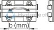
| Static torsional moment about the y-axis M0y | 1,1 · b |
| Ball chain | Without roller chain |
| Size S1 (profiled rail systems) | 18 |
| Operating temperature | -20 °C ... +80 °C |
| Size O1 thread diameter footnote | Fastening screws are not included. For screws ISO 4014 8.8, a washer according to ISO 7089 is required. |
| Dynamic torsional moment around the z-axis Mz | 3,6 · b |
| Static torsional moment about the z-axis M0z | 2,2 · b |
| Maximum permissible dynamic torsional moment about the x-axis Mx max | 0,42 · a |
| Maximum permissible static torsional moment about the x-axis M0x max | 0,7 · a |
| Height of runner block with guide rail | 26 |
| Dynamic torsional moment around the y-axis My | 2,1 · b |
| Dynamic torsional moment around the x-axis Mx | 2,1 · a |
| Static torsional moment about the x-axis M0x | 1,1 · a |
| Maximum dynamic load in z-direction Fz max | 850 |
| Size B (profiled rail systems) | 87 |
| Note: Maximum permissible speed vmax | For average load. |
| Maximum static load due to a resulting force in the z-direction F0z max | 1400 |
| Size O1 thread diameter | M8 |
| Maximum permissible dynamic torsional moment about the z-axis Mz max | 0,5 · b |
| Maximum permissible static torsional moment about the z-axis M0z max | 0,5 · b |
| Size H (profiled rail system) | 26 |
| Size H3 (profiled rail systems) | 2.5 |
| Productgroup ID | 17 |
| Maximum permissible dynamic torsional moment about the y-axis My max | 0,42 · b |
| Size H2 (profiled rail systems) | 11 |
| Maximum permissible static torsional moment about the y-axis M0y max | 0,7 · b |
| Size A1 (profiled rail systems) | 43 |
| Width of runner block | 31 |
| Length of runner block | 87 |
| Linear guide type | Cam roller guides |
| Size E1 (profiled rail systems) | 54 |
| Weight | 0.152 |
| Nominal size | 32 |
| Version | Cam roller guide |
| Size H1 (profiled rail systems) | 20.5 |

Technical data
|
Size |
32 | 52 | 52-h | 52-sh | |
|
Fy max |
N |
1000 | 2500 | 4500 | 8000 |
|
F0y max |
N |
1000 | 2500 | 4500 | 8000 |
|
Fz max |
N |
850 | 1500 | 2400 | 4800 |
|
F0z max |
N |
1400 | 2500 | 4000 | 7900 |
|
Mx max |
Nm |
0,42 · a | 0,75· a | 1,2 · a | 2,4 · a |
|
M0x max |
Nm |
0,7 · a | 1,2 · a | 2 · a | 3,9 · a |
|
My max |
Nm |
0,42 · b | 0,75· b | 1,2 · b | 2,4 · b |
|
M0y max |
Nm |
0,7 · b | 1,2 · b | 2 · b | 3,9 · b |
|
Mz max |
Nm |
0,5 · b | 1,2 · b | 2,2 · b | 4 · b |
|
M0z max |
Nm |
0,5 · b | 1,2 · b | 2,2 · b | 4 · b |
|
vmax 1) |
m/s |
10 | |||
|
amax |
m/s² |
50 | |||
|
Temperature stability |
-20 °C ... +80 °C | ||||
|
Weight |
kg |
0.13 | 0.34 | 0.51 | 0.61 |
| 1) | For average load. |
| Values Fmax and Mmax apply to four single bearing runner blocks. | |
| Attention: Not to be used for calculating the service life! | |
| For service life calculations use the load ratings and moments given in the tables. |
Load ratings and moments for calculating the service life
|
Size |
32 | 52 | 52-h | 52-sh | |
|
Cy |
N |
7335 | 17150 | 27900 | 31000 |
|
C0y |
N |
4560 | 10200 | 15400 | 18200 |
|
Cz |
N |
4300 | 10050 | 16775 | 18400 |
|
C0z |
N |
2200 | 4900 | 7630 | 8750 |
|
MX |
Nm |
2,1 · a | 5,0 · a | 8,3 · a | 9,3 · a |
|
M0x |
Nm |
1,1 · a | 2,4 · a | 3,8 · a | 4,4 · a |
|
My |
Nm |
2,1 · b | 5,0 · b | 8,3 · b | 9,2 · b |
|
M0y |
Nm |
1,1 · b | 2,4 · b | 3,8 · b | 4,3 · b |
|
Mz |
Nm |
3,6 · b | 8,5 · b | 13,9 · b | 15,5 · b |
|
M0z |
Nm |
2,2 · b | 5,1 · b | 7,6 · b | 9,1 · b |
| Load ratings and moments for calculating the service life when using four single bearing runner blocks. | |
| Observe maximum permissible loads due to forces and moments as shown in the "Technical data” table! |
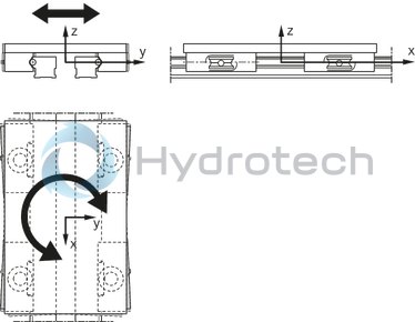
Legend
|
Symbol |
Description |
Unit |
Picture |
|
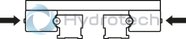
Cy |
Dynamic load capacity in y-direction |
N |
|
|
C0y |
Static load capacity in y-direction |
N |
|
|
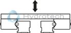
Cz |
Dynamic load capacity in z-direction |
N |
|
|
C0z |
Static load capacity in z-direction |
N |
|
|
Fy max |
Maximum dynamic load in y-direction |
N |
|
|
F0y max |
Maximum static load due to a resulting force in the y-direction |
N |
|
|
Fz max |
Maximum dynamic load in z-direction |
N |
|
|
F0z max |
Maximum static load due to a resulting force in the z-direction |
N |
|
|
Mx max |
Maximum permissible dynamic torsional moment about the x-axis |
Nm |

|
|
M0x max |
Maximum permissible static torsional moment about the x-axis |
Nm |
|
|
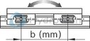
My max |
Maximum permissible dynamic torsional moment about the y-axis |
Nm |
|
|
M0y max |
Maximum permissible static torsional moment about the y-axis |
Nm |
|
|
Mz max |
Maximum permissible dynamic torsional moment about the z-axis |
Nm |
|
|
M0z max |
Maximum permissible static torsional moment about the z-axis |
Nm |
|
|
vmax |
Maximum permissible speed |
m/s |
|
|
amax |
Maximum acceleration travel |
m/s2 |
|
|
MX |
Dynamic torsional moment about the x-axis |
Nm |
|
|
M0x |
Static torsional moment about the x-axis |
Nm |
|
|
My |
Dynamic torsional moment about the y-axis |
Nm |
|
|
M0y |
Static torsional moment about the y-axis |
Nm |
|
|
Mz |
Dynamic torsional moment about the z-axis |
Nm |

|
|
M0z |
Static torsional moment about the z-axis |
Nm |
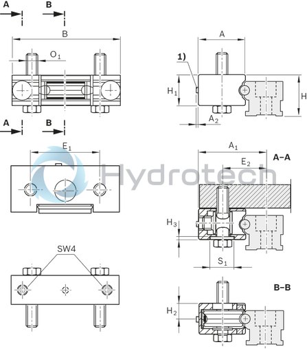
| 1) | Funnel-type lube nipple ø 3 mm |
Dimensions
|
Size |
32 | 52 | 52-h | 52-sh | |
|
A |
mm |
31 | 44.5 | 52 | 57 |
|
A1 |
mm |
43 | 65 | 72.5 | 77.5 |
|
A2 |
mm |
2 | |||
|
B |
mm |
87 | 104 | 118.5 | 123.5 |
|
E1 |
mm |
54 | 66 | 76 | 81 |
|
E2 |
mm |
27 | 42 | 45 | 47.5 |
|
H |
mm |
26 | 40 | 42 | |
|
H1 |
mm |
20.5 | 29.5 | 33.5 | |
|
H2 |
mm |
11 | 14.9 | 16.9 | |
|
H3 |
mm |
2.5 | 3 | ||
|
O1 1) |
mm |
M8 | M10 | M12 | |
|
S1 |
mm |
18 | 22 | 26 | |
| 1) | Fastening screws are not included. Screws according to ISO 4014 8.8 require a washer according to ISO 7089. |