


BOSCH REXROTH
R190213200
$332.13 USD
- BOSCH REXROTH
- Material:R190213200
- Model:C.ROL.R.BLOCK AL LWA-032-SNS-FN-E-0
Quantity in stock: 0
The Bosch Rexroth C.ROL.R.BLOCK AL LWA-032-SNS-FN-E-0 (R190213200) is a high-performance cam roller runner block designed for precision linear movement in automation and handling applications. This runner block features a slimline SNS format, with a length classified as normal and a standard height, providing an economic solution with standard load capacity. The body of the runner block is constructed from durable aluminum, ensuring a lightweight yet robust design suitable for various applications. With an economic accuracy class E, the C.ROL.R.BLOCK AL LWA-032-SNS-FN-E-0 does not come with initial lubrication or preservation, allowing for customization based on specific application requirements. The front lube unit includes low-friction seals on both sides and is equipped with lube nipples for ease of maintenance. This standard version runner block has been engineered to accommodate high loads in all four main directions, including moments about all axes. The unit allows for zero-clearance adjustment through eccentric spigots and features a two-row angular-contact ball bearing that is sealed and lubricated for life, offering longevity and reliability. The guide tracks are secured and made of corrosion-resistant precision steel shafts. This Bosch Rexroth runner block operates effectively within a temperature range of -10°C to +100°C and can handle dynamic torsional moments around the z-axis as well as static torsional moments about both y and z axes. It has been designed to withstand maximum permissible speeds, dynamic loads in both y and z directions, as well as static loads in these directions when paired with size E profiled rail systems. For automation technology applications requiring precise linear movement with high load capacity, the Bosch Rexroth C.ROL.R.BLOCK AL LWA-032-SNS-FN-E-0 offers an effective solution that balances performance with economic efficiency.
The cam roller runner block is characterized by the following product features: Format SNS, size 32, aluminum, accuracy economic, load class FN
The cam roller runner block is characterized by the following product features:
Size 32
Format SNS: Width = slimline, length = normal, height = standard
Runner block body made of aluminum
Standard load carrying capacity
Accuracy class E: Economic
Without preservation
Without initial lubrication
Attachment element, left (front reference edge): front lube unit with low-friction seal
Attachment element, right (front reference edge): Front lube unit with low-friction seal
Lube nipple included
Standard version
Overall length of the runner block = 119
Interchangeable element
Unpacked Weight: 0.561 kg
Rexroth cam roller guides were specially developed for handling and automation technology.
Product overview
| High load capacity in all four main directions of loading including moments about all axes |
| Wiper and lubrication units with large oil reservoir on both sides |
| Lube nipples possible on both sides |
| The runner block can be simply adjusted to zero clearance by means of eccentric spigots |
| Two-row angular-contact ball bearing, sealed and lubricated for life |
| Secured guide tracks made of corrosion-resistant precision steel shafts |
| Data Sheet | Download Data Sheet |
| 2D CAD | Download 2D CAD |
| 2D CAD | Download 2D CAD |
| 3D CAD | Download 3D CAD |
| 3D CAD | Download 3D CAD |
| Manual | Download Manual |
| Manual | Download Manual |
| Manual | Download Manual |
| Manual | Download Manual |
| Manual | Download Manual |
| Footnote for maximum static load due to a resulting force in the y-direction F0y max | Observe the permissible lateral force of the guide rail (see notes for mounting). |
| Maximum static load due to a resulting force in the y-direction F0y max | 1000 |
| Height of runner block | 13 |
| Size SW2 | 3 |
| Size E3 (profiled rail systems) | 54 |
| Dynamic load capacity in z-direction Cz | 4300 |
| Maximum operating temperature | |
| Static load capacity in z-direction C0z | 2200 |
| Size E2 (profiled rail systems) | 70 |
| Maximum dynamic load in y-direction Fy max | 1000 |
| Size SW3 | 4 |
| Dynamic load capacity in y-direction Cy | 7335 |
| Max. acceleration amax | 50 |
| Minimum operating temperature | |
| Static load capacity in y-direction C0y | 4560 |
| Size A (profiled rail systems) | 86 |
| Size SW1 | 10 |
| Self-aligning for compensation of misalignments | Without self-alignment |
| Maximum permissible linear speed vmax | 10 |
| Static torsional moment about the y-axis M0y | 66 |
| Lubrication | Without initial lubrication and without preservation |
| Ball chain | Without roller chain |
| Operating temperature | -20 °C ... +80 °C |
| Dynamic torsional moment around the z-axis Mz | 220 |
| Static torsional moment about the z-axis M0z | 137 |
| Maximum permissible dynamic torsional moment about the x-axis Mx max | 11 |
| Maximum permissible static torsional moment about the x-axis M0x max | 18 |
| Height of runner block with guide rail | 35.5 |
| Dynamic torsional moment around the y-axis My | 129 |
| Maximum static load due to a resulting force in the y-direction footnote | Observe the permissible lateral force of the guide rail (see notes for mounting). |
| Dynamic torsional moment around the x-axis Mx | 56 |
| Static torsional moment about the x-axis M0x | 29 |
| Maximum dynamic load in y-direction footnote | Observe the permissible lateral force of the guide rail (see notes for mounting). |
| Maximum dynamic load in z-direction Fz max | 850 |
| Size B2 (profiled rail systems) | 7 |
| Size B (profiled rail systems) | 112 |
| Note: Maximum permissible speed vmax | For average load. |
| Preload class | C0 – Without preload (clearance) |
| Maximum static load due to a resulting force in the z-direction F0z max | 1400 |
| Maximum permissible dynamic torsional moment about the z-axis Mz max | 30 |
| Maximum permissible static torsional moment about the z-axis M0z max | 30 |
| Size B1 | 92 |
| Size H (profiled rail system) | 35.5 |
| Size H3 (profiled rail systems) | 29.5 |
| Productgroup ID | 17 |
| Maximum permissible dynamic torsional moment about the y-axis My max | 26 |
| Size H2 (profiled rail systems) | 20.5 |
| Maximum permissible static torsional moment about the y-axis M0y max | 42 |
| Size E4 | 60 |
| Runner block or guide rail | Runner block |
| Width of runner block | 86 |
| Length of runner block | 112 |
| Linear guide type | Cam roller guides |
| Size E1 (profiled rail systems) | 59 |
| Weight | 0.561 |
| Nominal size | 32 |
| Version | Cam roller guide |
| Size H1 (profiled rail systems) | 13 |
| Note: Maximum dynamic load in y-direction Fy max | Observe the permissible lateral force of the guide rail (see instruction for mounting). |

Technical data
|
Size |
20 | 25 | 32 | 52 | 52-h | 52-sh | |
|
Fy max 1) |
N |
700 | 1000 | 2500 | 4500 | 8000 | |
|
F0y max 1) |
N |
700 | 1000 | 2500 | 4500 | 8000 | |
|
Fz max |
N |
400 | 850 | 1500 | 2400 | 4800 | |
|
F0z max |
N |
600 | 660 | 1400 | 2500 | 4000 | 7900 |
|
Mx max |
Nm |
3,2 | 3,8 | 11 | 32 | 50 | 101 |
|
M0x max |
Nm |
4,8 | 6 | 18 | 52 | 84 | 166 |
|
My max |
Nm |
6,8 | 9 | 26 | 45 | 126 | 288 |
|
M0y max |
Nm |
10,2 | 15 | 42 | 75 | 210 | 474 |
|
Mz max |
Nm |
12 | 16 | 30 | 75 | 236 | 480 |
|
M0z max |
Nm |
12 | 16 | 30 | 75 | 236 | 480 |
|
vmax 2) |
m/s |
10 | |||||
|
amax |
m/s² |
50 | |||||
|
Temperature stability |
-20 °C ... +80 °C | ||||||
|
Weight |
kg |
0.2 | 0.25 | 0.56 | 1.5 | 2.6 | 3.3 |
| 1) | Observe the permissible lateral force of the guide rail (see notes for mounting). |
| 2) | For average load. |
| Attention: Not to be used for the life expectancy calculation! | |
| For service life calculations use the load ratings and moments given in the tables for service life calculations. |
Load ratings and moments for calculating the service life
|
Size |
20 | 25 | 32 | 52 | 52-h | 52-sh | |
|
Cy |
N |
2300 | 2550 | 7335 | 17150 | 27900 | 31000 |
|
C0y |
N |
1600 | 1780 | 4560 | 10200 | 15400 | 18200 |
|
Cz |
N |
1336 | 1357 | 4300 | 10050 | 16775 | 18400 |
|
C0z |
N |
783 | 803 | 2200 | 4900 | 7630 | 8750 |
|
MX |
Nm |
10,7 | 13 | 56 | 211 | 352 | 390 |
|
M0x |
Nm |
6,3 | 7,6 | 29 | 103 | 160 | 184 |
|
My |
Nm |
22,7 | 30,5 | 129 | 301 | 880 | 1100 |
|
M0y |
Nm |
13,3 | 18 | 66 | 147 | 400 | 520 |
|
Mz |
Nm |
39 | 57 | 220 | 515 | 1465 | 1860 |
|
M0z |
Nm |
27 | 40 | 137 | 306 | 808 | 1100 |
| Observe maximum permissible loads due to forces and moments as shown in the "Technical data” table! |
Legend
|
Symbol |
Description |
Unit |
Picture |
|
Cy |
Dynamic load capacity in y-direction |
N |

|
|
C0y |
Static load capacity in y-direction |
N |
|
|
Cz |
Dynamic load capacity in z-direction |
N |

|
|
C0z |
Static load capacity in z-direction |
N |
|
|
Fy max |
Maximum dynamic load in y-direction |
N |
|
|
F0y max |
Maximum static load due to a resulting force in the y-direction |
N |
|
|
Fz max |
Maximum dynamic load in z-direction |
N |
|
|
F0z max |
Maximum static load due to a resulting force in the z-direction |
N |
|
|
Mx max |
Maximum permissible dynamic torsional moment about the x-axis |
Nm |

|
|
M0x max |
Maximum permissible static torsional moment about the x-axis |
Nm |
|
|
My max |
Maximum permissible dynamic torsional moment about the y-axis |
Nm |
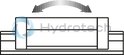
|
|
M0y max |
Maximum permissible static torsional moment about the y-axis |
Nm |
|
|
Mz max |
Maximum permissible dynamic torsional moment about the z-axis |
Nm |
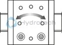
|
|
M0z max |
Maximum permissible static torsional moment about the z-axis |
Nm |
|
|
vmax |
Maximum permissible speed |
m/s |
|
|
amax |
Maximum acceleration travel |
m/s2 |
|
|
MX |
Dynamic torsional moment about the x-axis |
Nm |
|
|
M0x |
Static torsional moment about the x-axis |
Nm |
|
|
My |
Dynamic torsional moment about the y-axis |
Nm |
|
|
M0y |
Static torsional moment about the y-axis |
Nm |
|
|
Mz |
Dynamic torsional moment about the z-axis |
Nm |
|
|
M0z |
Static torsional moment about the z-axis |
Nm |
Rigidity
An increased rigidity can be achieved with higher pre-tensioning force by using eccentric setting.
Acceleration
High accelerations are permitted if slippage is avoided. For this, the pre-tensioning force FV by increasing the eccentric setting; see diagram.
Attention: The maximum permissible load is reduced by the increase of the pre-tensioning force.
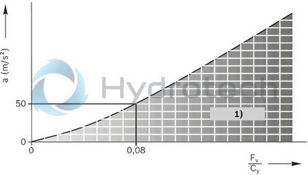
| 1) | Permissible range |
| 2) | a = acceleration |
| 3) | Fv/Cy = standard setting |

| 1) | Eccentric setting |
| Lube nipples | |
| Sizes 20 – 32: | |
| - Funnel-type lube nipple | |
| - Form B - thread M3 | |
| Sizes 52 – 52-sh: | |
| - Hydraulic-type lube nipple | |
| - BM 6 DIN 71412 | |
| Connection possible on two sides. |
Dimensions
|
Size |
20 | 25 | 32 | 52 | 52-h | 52-sh | |
|
A |
mm |
56 | 65 | 86 | 130 | 145 | 155 |
|
B |
mm |
79 | 95 | 112 | 136 | 186 | 205 |
|
B1 |
mm |
59 | 75 | 92 | 104 | 154 | 173 |
|
B2 |
mm |
7 | 16 | ||||
|
E1 |
mm |
39 | 50 | 59 | 90 | 105 | 115 |
|
E2 |
mm |
49 | 60 | 70 | 110 | 140 | |
|
E3 |
mm |
34 | 40 | 54 | 83.3 | 90 | 95 |
|
E4 |
mm |
34 | 45 | 60 | 105 | 120 | |
|
E5 |
M5 | M8 | M10 | M12 | |||
|
H |
mm |
22 | 25 | 35.5 | 54.3 | 60.4 | |
|
H1 |
mm |
8.5 | 9 | 13 | 19.4 | 24 | |
|
H2 |
mm |
13 | 14.4 | 20.5 | 29.2 | 35.3 | |
|
H3 |
mm |
20 | 22.3 | 29.5 | 42.2 | 51 | |
|
SW1 |
mm |
7 | 10 | 16 | 18 | ||
|
SW2 |
mm |
2 | 3 | 4 | 6 | ||
|
SW3 |
mm |
2 | 4 | 6 | 8 | ||
Centric pins are already tightened when delivery.