


BOSCH REXROTH
R181064251
$6,081.73 USD
- BOSCH REXROTH
- Material:R181064251
- Model:KWH 6505 BS2A
Quantity in stock: 0
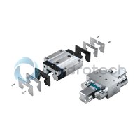
The Bosch Rexroth CLAMPING ELEMENT (R181064251) is a hydraulic clamping unit designed for dynamic and static stabilization in the axial direction of roller rail systems. This clamping element can be utilized with all SNS roller guide rails, ensuring broad compatibility and application flexibility. It boasts a compact design that adheres to DIN standards, allowing for easy integration into various systems. The KWH 6505 BS2A model features a solid, rigid steel housing that is chemically nickel-plated, providing robustness and resistance to harsh conditions. It offers very high axial holding forces, which contribute to its effectiveness in securing components with precision. The unit is equipped with special pressure diaphragm technology that ensures maximum functional reliability without pressure losses or leakage, enhancing its operational longevity. With the ability to perform up to 1 million clamping cycles (Bd value), this clamping element promises durability and consistent performance over time. It has integrated positive-locking contact profiles that deliver maximum axial rigidity, contributing to high positioning accuracy. The hydraulic pressure for the unit can be continuously adjusted from 50 to 350 bar, giving users control over the clamping force as per their specific requirements. The device also includes an all-around sealing feature for additional protection against contaminants. For convenience, it is threaded on both sides for the hydraulic connection and supports a nominal size according to the application's demands. Its functional principle involves using hydraulic oil pressure applied through a piston principle directly onto the flanks of the Roller Guide Rail for secure clamping, while a pre-tensioned return spring ensures quick decompression cycles when necessary. This Bosch Rexroth CLAMPING ELEMENT is an essential accessory for profiled rail systems requiring reliable and precise axial stabilization through hydraulic clamping mechanisms.
Hydraulic clamping unit KWH, 65
Hydraulic clamping unit KWH, SLS for roller rail systems
Size = 65
Can be used on all SNS roller guide rails
Unpacked Weight: 13.185 kg
Functional principle
Hydraulic pressure: 50 - 150 bar
Clamps and brakes with pressure
The large-scale clamping profiles are pressed directly through the hydraulic oil via a piston principle to the flanks of the Roller Guide Rail.
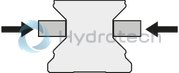
Hydraulic pressure: 0 bar
Decompression with spring force
A pre-tensioned return spring allows for short decompression cycles.
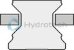
| Very high axial holding forces |
| Dynamic and static stabilization in the axial direction |
| Compact design, compatible with DIN 645 |
| Clamps and brakes with pressure |
| Can be used on all SNS roller guide rails |
| Threaded on both sides for the hydraulic connection |
| Solid, rigid steel housing, chemically nickel-plated |
| High positioning accuracy |
| Integrated all-round sealing |
| Special pressure diaphragm technology for maximum functional reliability without pressure losses or leakage |
| Integrated positive-locking, large-surface contact profiles for maximum axial rigidity |
| 10 million clamping cycles (B10d value) |
| 10 million clamping cycles (B10d value) |
| 3D CAD | Download 3D CAD |
| 3D CAD | Download 3D CAD |
| Manual | Download Manual |
| Manual | Download Manual |
| Manual | Download Manual |
| Manual | Download Manual |
| Manual | Download Manual |
| Manual | Download Manual |
| Manual | Download Manual |
| Manual | Download Manual |
| Manual | Download Manual |
| Manual | Download Manual |
| Displacement footnote | Pro Klemmvorgang |
| Size B1 (profiled rail systems) | 227 |
| Size H (profiled rail system) | 90 |
| Holding force | 22700 |
| Height of runner block | 76 |
| Max. holding force | 22700 |
| Productgroup ID | 17 |
| Size F | 20 |
| Size B3 | 245.1 |
| Size E2 (profiled rail systems) | 120 |
| Permissible ambient temperature (max) | |
| Footnote 2 holding force | 150 bar |
| Permissible ambient temperature | 0 °C ... +70 °C |
| Displacement | 3.8 |
| Max. hydraulic operating pressure: | 150 |
| Size A (profiled rail systems) | 126 |
| Footnote 1 holding force | The inspection is done in a mounted state with a lubricated layer (ISO-VG 68). For permissible holding forces see "Technical data and calculations". |
| Permissible ambient temperature (min) | |
| Width of runner block | 126 |
| Size N3 (profiled rail systems) | 21 |
| Height of runner block with guide rail | 90 |
| Linear guide type | Accessories for profiled rail systems |
| Type clamping and braking units | Hydraulic |
| Size E1 (profiled rail systems) | 76 |
| Accessories for profiled rail systems | Clamping and braking units |
| Size S2 thread diameter (profiled rail systems) | M16 |
| Weight | 13.185 |
| Size H1 (profiled rail systems) | 76 |
| Nominal size | 65 |
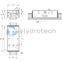
General technical data
|
Size |
65 | |
|
Holding force 1) 2) |
N |
22700 |
|
Displacement 3) |
cm³ |
3.8 |
|
Max. hydraulic operating pressure |
bar |
150 |
|
Mass |
kg |
15.4 |
|
Operating conditions |
||
|
Size |
65 | |
|
Permissible ambient temperature (min ... max) |
0 °C ... +70 °C | |
| 1) | The inspection is done in a mounted state with a lubricated layer (ISO-VG 68). For permissible holding forces see “Technical data and calculations.” |
| 2) | At 150 bar |
| 3) | Per clamping |
Technical data and calculations
Clamping of heavy handling systems clamping of machine tables from heavily machined machining centers
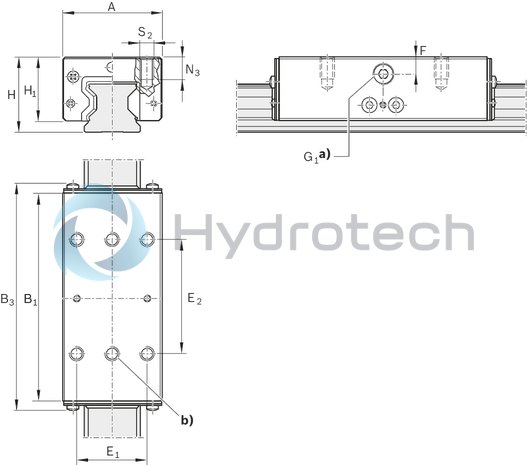
| a) | Hydraulic connection*) G1 on two sides |
| b) | In addition, both middle mounting holes must be used! |
| *) Only one connection needed. | |
| All connections sealed upon delivery. |
Dimensions
|
Size |
65 | |
|
A |
mm |
126 |
|
B1 |
mm |
227 |
|
B3 |
mm |
238 |
|
E1 |
mm |
76 |
|
E2 |
mm |
120 |
|
F |
mm |
20 |
|
G1 |
3 Verstellelemente |
1/4" |
|
H |
mm |
90 |
|
H1 |
mm |
76 |
|
N3 |
mm |
21 |
|
S2 |
M16 |