


BOSCH REXROTH
R181054260
$3,068.88 USD
- BOSCH REXROTH
- Material:R181054260
- Model:MK 5505 AR
Quantity in stock: 0
The Bosch Rexroth CLAMPING ELEMENT MK 5505 AR (R181054260) is a sophisticated pneumatic clamping unit designed for use with roller rail systems. This device ensures dynamic and static stabilization in the axial direction, offering high axial and horizontal rigidity for precise positioning and robust operation. The clamping element is compatible with various sizes of Bosch Rexroth's profiled rail systems, including sizes H, E, A, d, N, B, and S thread diameter systems. Featuring a chemically nickel-plated steel housing, the unit boasts a durable construction suitable for demanding applications. It operates using compressed air to press clamping profiles against the web surfaces of roller guide rails through a dual-acting gate valve gear mechanism. The air pressure required for clamping is adjustable from 2 to 8 bar, while decompression is facilitated by a pre-tensioned return spring enabling short decompression cycles. This model is capable of withstanding up to 1 million clamping cycles without reaching its Bd value when not using the PLUS connection. It has an air consumption norm of less than one liter per cycle and can operate within a permissible ambient temperature range of -10°C to +80°C. The unit's size and weight specifications ensure compatibility with various system configurations while maintaining ease of mounting and operational efficiency. With its spring energy holding force and continuous pressure adjustability, the Bosch Rexroth CLAMPING ELEMENT MK 5505 AR (R181054260) represents an ideal solution for users seeking reliable and precise control in their linear motion applications. Its design allows for easy integration into existing setups while providing significant improvements in performance and longevity.
Pneumatic clamping unit MK, 55
Pneumatic clamping unit MK for roller rail systems
Size = 55
Can be used on all SNS roller guide rails
Unpacked Weight: 1.928 kg
Functional principle
Air pressure: 4.0 - 8 bar
Clamps with air pressure
For MK, the clamping profiles are pressed via compressed air across a dual acting gate valve gear mechanism to the web surfaces of the roller guide rail.
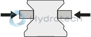
Air pressure: 0 bar
Decompression with spring force
A pre-tensioned return spring allows for short decompression cycles.
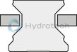
| Dynamic and static stabilization in the axial direction |
| Can be used on all SNS roller guide rails |
| Easy mounting |
| Clamps with compression (pneumatic) The clamping profiles are pressed by compressed air via a dual acting gate valve gear mechanism. |
| Chemically nickel-plated steel housing |
| High axial and horizontal rigidity |
| Precise positioning |
| Continuously adjustable pressure from 4 - 8 bar |
| Can be used on all SNS roller guide rails |
| 5 million clamping cycles (B10d value) – the B10d value is not attained with the PLUS connection |
| Short decompression cycles |
| 3D CAD | Download 3D CAD |
| 3D CAD | Download 3D CAD |
| Manual | Download Manual |
| Manual | Download Manual |
| Manual | Download Manual |
| Manual | Download Manual |
| Manual | Download Manual |
| Manual | Download Manual |
| Manual | Download Manual |
| Manual | Download Manual |
| Manual | Download Manual |
| Manual | Download Manual |
| Size H (profiled rail system) | 70 |
| Height of runner block | 57 |
| Air consumption (normal liter) standard air port | 0.041 |
| Productgroup ID | 17 |
| Size E3 (profiled rail systems) | 9.5 |
| Spring energy holding force with standard air port | 2250 |
| Size E2 (profiled rail systems) | 30 |
| Permissible ambient temperature (max) | |
| Permissible ambient temperature | 0 °C ... +70 °C |
| Footnote for spring energy holding force with standard air port | Holding force by spring energy at 6 bar. The inspection is done in a mounted state with a lubricated layer (ISO-VG 68). |
| Size A (profiled rail systems) | 128 |
| Size F1 | 17 |
| Size F2 | 19.5 |
| Permissible ambient temperature (min) | |
| Width of runner block | 128 |
| Size d (profiled rail systems) | 5.5 |
| Size N3 (profiled rail systems) | 15 |
| Length of runner block | 49 |
| Height of runner block with guide rail | 70 |
| Linear guide type | Accessories for profiled rail systems |
| Type clamping and braking units | Pneumatic |
| Size B (profiled rail systems) | 49 |
| Max. pneumatic operating pressure: | 8 |
| Size E1 (profiled rail systems) | 30 |
| Footnote size H1 | For roller runner block .H. (...High...) Spacer plate necessary. |
| Accessories for profiled rail systems | Clamping and braking units |
| Size S2 thread diameter (profiled rail systems) | M10 |
| Weight | 1.928 |
| Size H1 (profiled rail systems) | 57 |
| Nominal size | 55 |
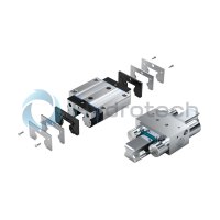

General technical data
|
Size |
25 | 35 | 45 | 55 | 65 | |
|
Spring energy holding force with standard air port 1) |
N |
1200 | 2000 | 2250 | ||
|
Air consumption (normal liter) standard air port |
dm³/stroke |
0.021 | 0.031 | 0.041 | ||
|
Max. pneumatic operating pressure |
bar |
8 | ||||
|
Mass |
kg |
0.45 | 0.88 | 1.7 | 1.95 | 2.68 |
|
Operating conditions |
||||||
|
Size |
25 | 35 | 45 | 55 | 65 | |
|
Permissible ambient temperature (min ... max) |
0 °C ... +70 °C | |||||
| 1) | Holding force at 6 bar. The inspection is done in a mounted state with a lubricated layer (ISO-VG 68). |
Circuit1) with standard air connection
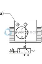
1) Holding force at 6 bar. The inspection is done in a mounted state with a lubricated layer (ISO-VG 68).
a) Air filter
1 Air connection
2 Working connection
3 Exhaust
Pneumatic clamping of machine axes Table crossbars in the timber industry Positioning of lifting gear
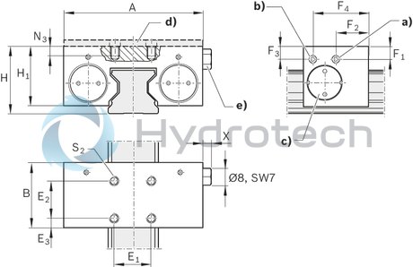
| a) | Air connection*) M5 on two sides for release pressure |
| b) | Connection*) M5 on two sides for air filter |
| c) | Adjusting screw on two sides |
| d) | Spacer plate (accessory) for MK |
| e) | Air filter: connection M5 (possible on two sides) |
| *) Only one connection needed. | |
| All connections sealed upon delivery. |
Dimensions
|
Size |
25 | 35 | 45 | 55 | 65 | |
|
A |
mm |
75 | 100 | 120 | 128 | 138 |
|
B |
mm |
35 | 39 | 49 | ||
|
E1 |
mm |
20 | 24 | 26 | 30 | |
|
E2 |
mm |
20 | 24 | 26 | 30 | |
|
E3 |
mm |
5 | 7.5 | 11.5 | 9.5 | |
|
F1 |
mm |
6.5 | 11 | 14.5 | 17 | 14.5 |
|
F2 |
mm |
17.5 | 14.5 | 19.5 | ||
|
F3 |
mm |
6.5 | 12 | 14.5 | 17 | 14.5 |
|
F4 |
mm |
30 | 24.5 | 29.5 | ||
|
H |
mm |
36 | 48 | 60 | 70 | 90 |
|
H1 1) |
mm |
32.5 | 44 | 52 | 57 | 73.5 |
|
N3 |
mm |
8 | 10 | 15 | 20 | |
|
S2 |
M6 | M8 | M10 | |||
|
X |
mm |
5.5 | ||||
| 1) | for roller runner block .H. (...high...) Spacer plate necessary. |
Note for mounting
Make sure the connection structure is rigid. Use only purified air. The prescribed filter mesh size is 25 μm. Observe the mounting instructions prior to commissioning.Spacer plate for clamping units MK, MKS
R1619 .40 65
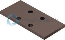
Spacer plate for clamping units MK, MKS
R1619 .40 65
Suitable for assembly with high ball runner blocks SNH R1621 and SLH R1624. Suitable for assembly with high roller runner blocks SNH R1821 and SLH R1824.CAD data
Service