


BOSCH REXROTH
R181024060
$1,478.41 USD
- BOSCH REXROTH
- Material:R181024060
- Model:MKS 2505 AR
Quantity in stock: 0
The Bosch Rexroth CLAMPING ELEMENT MKS 2505 AR (R181024060) is a high-precision pneumatic clamping unit designed for dynamic and static stabilization in the axial direction. It offers easy mounting capabilities and can be used on all SNS roller guide rails, providing a versatile solution for various applications that require precise positioning and increased holding force. The clamping element operates efficiently with an air pressure range of 4 to 8 bar, engaging the clamping mechanism via a dual-action gate valve gear mechanism supported by two spring assemblies when there is a drop in pressure. This ensures secure clamping even without pressurization due to the spring energy accumulator. Featuring a chemically nickel-plated steel housing, this unit provides high axial and horizontal rigidity, which contributes to its precise positioning capabilities and robustness in operation. It has been engineered for both high dynamics and powerful drive performance, ensuring long service life with up to 1 million clamping cycles. The additional airplus port allows for higher holding force when additional air admission is required, which can be controlled using either a 3 or 4-way directional control valve. The Bosch Rexroth CLAMPING ELEMENT MKS is compatible with various sizes of profiled rail systems including Size B, H, E, A, D, d, N profiled rail systems as well as Size S thread diameter profiled rail systems with an M weight. It also features an integrated quick-exhaust valve for short reaction times during decompression. With its nominal size and ability to operate under a wide range of ambient temperatures from -10°C up to +80°C, this clamping element is suitable for diverse industrial applications that demand reliability and efficiency in securing components during machine operations.
Pneumatic clamping unit MKS, 25
Pneumatic clamping unit MKS for roller rail systems
Size = 25
Can be used on all SNS roller guide rails
Unpacked Weight: 0.484 kg
Functional principle
Air pressure: 0 bar
Clamps with spring force
In the event of a pressure drop, the MKS clamps via a dual acting gate valve gear mechanism, each with one spring assembly (spring energy accumulator).
An integrated quick-exhaust valve provides for short reaction times.
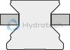
Air pressure: 5.5 - 8 bar
Decompression with air pressure
The clamping profiles are held apart by the compressed air.
Free movement is possible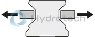
| Dynamic and static stabilization in the axial direction |
| Can be used on all SNS roller guide rails |
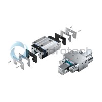
| Easy mounting |
| Clamps without pressurization (spring energy). In the event of a pressure drop, it clamps via the dual-action gate valve gear mechanism with two spring assemblies. |
| Chemically nickel-plated steel housing |
| High axial and horizontal rigidity |
| Precise positioning |
| Higher holding force due to the air-plus port |
| Can be used on all SNS roller guide rails |
| 5 million clamping cycles (B10d value) – the B10d value is not attained with the PLUS connection |
| 3D CAD | Download 3D CAD |
| 3D CAD | Download 3D CAD |
| Manual | Download Manual |
| Manual | Download Manual |
| Manual | Download Manual |
| Manual | Download Manual |
| Manual | Download Manual |
| Manual | Download Manual |
| Manual | Download Manual |
| Manual | Download Manual |
| Manual | Download Manual |
| Manual | Download Manual |
| Size B1 | 57.3 |
| Size H (profiled rail system) | 36 |
| Height of runner block | 32.5 |
| Air consumption (normal liter) standard air port | 0.021 |
| Footnote for spring energy holding force with air-plus port | Holding force achieved by spring energy. The inspection is done in a mounted state with a lubricated layer (ISO-VG 68). |
| Productgroup ID | 17 |
| Size E3 (profiled rail systems) | 5 |
| Size H2 (profiled rail systems) | 20 |
| Height of guide rail H2 | 20 |
| Size A1 (profiled rail systems) | 49 |
| Spring energy holding force with standard air port | 750 |
| Size E2 (profiled rail systems) | 20 |
| Permissible ambient temperature (max) | |
| Permissible ambient temperature | 0 °C ... +70 °C |
| Footnote for spring energy holding force with standard air port | Holding force achieved by spring energy. The inspection is done in a mounted state with a lubricated layer (ISO-VG 68). |
| Size A (profiled rail systems) | 75 |
| Size F1 | 6.5 |
| Size F2 | 30 |
| Permissible ambient temperature (min) | |
| Width of runner block | 75 |
| Size D | 22 |
| Size d (profiled rail systems) | 5.5 |
| Spring energy holding force with air-plus port footnote 2 | Increased holding force by additional air admission at air-plus port with 6.0 bar. Switching via 5/2 or 5/3-way directional control valve. |
| Size N3 (profiled rail systems) | 8 |
| Length of runner block | 35 |
| Height of runner block with guide rail | 36 |
| Spring energy holding force with air-plus port | 1500 |
| Air consumption (normal liter) air-plus port | 0.068 |
| Linear guide type | Accessories for profiled rail systems |
| Release pressure min. | 5.5 |
| Type clamping and braking units | Pneumatic |
| Size B (profiled rail systems) | 35 |
| Max. pneumatic operating pressure: | 8 |
| Size E1 (profiled rail systems) | 20 |
| Footnote size H1 | For roller runner block .H. (...High...) Spacer plate necessary. |
| Accessories for profiled rail systems | Clamping and braking units |
| Size S2 thread diameter (profiled rail systems) | M6 |
| Weight | 0.484 |
| Size H1 (profiled rail systems) | 32.5 |
| Nominal size | 25 |

General technical data
|
Size |
25 | 35 | 45 | 55 | 65 | |
|
Spring energy holding force with standard air port 1) |
N |
750 | 1250 | 1450 | ||
|
Spring energy holding force with air-plus port 1) 2) |
N |
1500 | 3250 | 3300 | ||
|
Air consumption (normal liter) standard air port |
dm³/stroke |
0.021 | 0.031 | 0.041 | ||
|
Air consumption (normal liter) air-plus port |
dm³/stroke |
0.068 | 0.129 | 0.175 | ||
|
Max. pneumatic operating pressure |
bar |
8 | ||||
|
Release pressure min. |
bar |
5.5 | ||||
|
Mass |
kg |
0.5 | 1 | 1.84 | 2.08 | 2.86 |
|
Operating conditions |
||||||
|
Size |
25 | 35 | 45 | 55 | 65 | |
|
Permissible ambient temperature (min ... max) |
0 °C ... +70 °C | |||||
| 1) | Holding force by spring energy. The inspection is done in a mounted state with a lubricated layer (ISO-VG 68). |
| 2) | Increased holding force by additional air admission at air-plus port with 6.0 bar. Circuit across 5/2- or 5/3-way directional control valve. |
Circuit1) with standard air connection
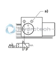
1) Holding force by spring energy. The inspection is done in a mounted state with a lubricated layer (ISO-VG 68).
a) Air filter
1 Air connection
2 Working connection
3 Exhaust
Circuit1) for air-plus port
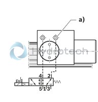
1) Increased holding force by additional air admission at air-plus port with 6.0 bar. Circuit across 5/2- or 5/3-way directional control valve.
a) Air-plus port
1 Air connection
2 4 Working connections
3 5 Exhaust
Pneumatic clamping of machine axes Table crossbars in the timber industry Positioning of lifting gear
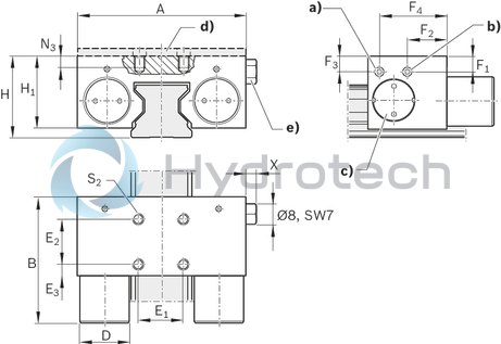
| a) | Air connection*) M5 on two sides for release pressure |
| b) | Connection*) M5 on two sides for Plus-Air connection or air filter |
| c) | Adjusting screw on two sides |
| d) | Spacer plate (accessory) for MKS |
| e) | Air filter: connection M5 (possible on two sides) |
| *) Only one connection needed. | |
| All connections sealed upon delivery. |
Dimensions
|
Size |
25 | 35 | 45 | 55 | 65 | |
|
A |
mm |
75 | 100 | 120 | 128 | 138 |
|
A1 |
mm |
49 | 68 | 78.8 | 86.8 | 96.8 |
|
B |
mm |
35 | 39 | 49 | ||
|
B1max |
mm |
57.3 | 67.5 | 82.5 | ||
|
D |
mm |
22 | 28 | 30 | ||
|
E1 |
mm |
20 | 24 | 26 | 30 | |
|
E2 |
mm |
20 | 24 | 26 | 30 | |
|
E3 |
mm |
5 | 7.5 | 11.5 | 9.5 | |
|
F1 |
mm |
6.5 | 12 | 14.5 | 17 | 14.5 |
|
F2 |
mm |
30 | 24.5 | 29.5 | ||
|
F3 |
mm |
6.5 | 11 | 14.5 | 17 | 14.5 |
|
F4 |
mm |
17.5 | 14.5 | 19.5 | ||
|
H |
mm |
36 | 48 | 60 | 70 | 90 |
|
H1 1) |
mm |
32.5 | 44 | 52 | 57 | 73.5 |
|
H2 |
mm |
20 | 28 | 35.5 | 40 | 55 |
|
N3 |
mm |
8 | 10 | 15 | 20 | |
|
S2 |
M6 | M8 | M10 | |||
|
X |
mm |
5.5 | ||||
| 1) | for roller runner block .H. (...high...) Spacer plate necessary. |
Note for mounting
Make sure the connection structure is rigid. Use only purified air. The prescribed filter mesh size is 25 μm. Observe the mounting instructions prior to commissioning.Spacer plate for clamping units MK, MKS
R1619 .40 65
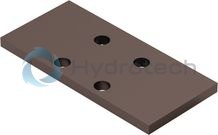
Spacer plate for clamping units MK, MKS
R1619 .40 65
Suitable for assembly with high ball runner blocks SNH R1621 and SLH R1624. Suitable for assembly with high roller runner blocks SNH R1821 and SLH R1824.CAD data
Service