


BOSCH REXROTH
R170342070
$254.34 USD
- BOSCH REXROTH
- Material:R170342070
- Model:LSAHO-SH-20-VD
Quantity in stock: 0
The Bosch Rexroth LINEAR-SET LSAHO-SH-20-VD (R170342070) is a high-quality linear motion set designed for precise and heavy-duty applications. This fully sealed linear set is constructed with lightweight precision aluminum housing and incorporates super linear bushings SH, which are capable of compensating for misalignments up to a specified tolerance. The shaft diameter 'd' ensures robust performance, while the standard version's design facilitates ease of maintenance with its relubricatable feature. This LINEAR-SET is particularly noted for its ability to handle dynamic loads efficiently, as indicated by the dynamic load capacity 'C', which applies to the main direction of loading. The product also boasts an impressive maximum acceleration 'amax' and can operate within a wide range of ambient temperatures, from minimum to maximum degrees Celsius without compromising on performance. The outer diameter 'D' is tailored to size 'H', ensuring compatibility with various applications. Furthermore, the LINEAR-SET has been engineered to withstand significant static loads with its substantial static load rating 'C'. The breakaway force and maximum permissible linear speed 'vmax' are indicative of the unit's capability to operate smoothly under varied operational conditions. This product falls under Productgroup ID that pertains to linear sets equipped with linear bushings. The format of these bushings is HO – Heavyduty, open – signifying their durability and suitability for open configurations. Additionally, this model has been secured with bolts and offers low frictional drags generated by integrated wiper seals when not under radial load, as reflected in the footnote regarding friction force 'FR'. Weighing in at just . kilograms, this Bosch Rexroth Linear Set combines lightweight construction with robust performance features, making it an ideal solution for those seeking reliable linear motion components that are both efficient and durable.
Linear set (aluminum), HO-SH-20, fully sealed
Linear set (aluminum)
Heavy-duty, open
With super LB SH
Shaft diameter d = 20
Fully sealed
Version: Standard
Unpacked Weight: 0.255 kg
| Lightweight precision housing (aluminum) |
| super linear bushings SH |
| Compensate for misalignments of up to 30 ft |
| Fully sealed |
| Secured with bolt |
| Relubricatable |
| Data Sheet | Download Data Sheet |
| 2D CAD | Download 2D CAD |
| 2D CAD | Download 2D CAD |
| 3D CAD | Download 3D CAD |
| 3D CAD | Download 3D CAD |
| Manual | Download Manual |
| Manual | Download Manual |
| Manual | Download Manual |
| Manual | Download Manual |
| Manual | Download Manual |
| Size V | 5 |
| Footnote shaft radial clearance h6 | Clamped (fastened). |
| Series | Super SH |
| Footnote friction force FR | Frictional drags generated by linear bushings with integrated wiper seals on two sides when not under radial load. The frictional drags depend on speed and lubrication. |
| Size E1 | 45 |
| Footnote dynamic load capacity C | The load capacities apply for the main direction of loading. |
| Size H | 25 |
| Max. acceleration amax | 150 |
| Permissible ambient temperature | -20 °C ... +80 °C |
| Outer diameter D | 32 |
| Size H3 | 10 |
| Breakaway force | 7.5 |
| Size L3 | 16 |
| Size H4 | 3.5 |
| Maximum permissible linear speed vmax | 5 |
| Size D | 32 |
| Footnote static load capacity C0 | The load capacities apply for the main direction of loading. |
| Size N1 | 24 |
| Static load rating C0 | 2530 |
| Size M | 30 |
| Friction force | 4 |
| Size A | 60 |
| Productgroup ID | 17 |
| Size N2 | 18 |
| Size W | 9.5 |
| Size E3 | 50 |
| Permissible ambient temperature (max) | |
| Size E2 | 32 |
| Size E4 | 15 |
| Angle α | 54 |
| Size SW | 2.5 |
| Permissible ambient temperature (min) | |
| Size S | 6.6 |
| Shaft diameter d | 20 |
| Linear guide type | Linear bushing and shaft |
| Filter for linear bushings and shafts | Linear sets with linear bushings |
| Format of linear bushings | HO – Heavy-duty, open |
| Dynamic load capacity C | 3530 |
| Size L | 46 |
| Size S2 | 5 |
| Weight | 0.255 |
| Size D1 with tolerance | |
| Size H1 | 42 |

General technical data
|
Ø d |
mm |
20 | 25 | 30 | 40 | 50 |
|
amax |
m/s² |
150 | ||||
|
vmax |
m/s |
5 | ||||
|
m |
kg |
0.26 | 0.51 | 0.79 | 1.56 | 2.6 |
|
FR 1) |
N |
4 | 4.5 | 6 | 7.5 | 9 |
|
Breakaway force |
N |
7.5 | 10.5 | 13.5 | 18 | 22.5 |
|
Shaft radial clearance h6 2) |
µm |
+ 31 - 2 |
+ 35 - 3 |
|||
|
Operating conditions |
||||||
|
Permissible ambient temperature (min ... max) |
-20 °C ... +80 °C | |||||
| 1) | Frictional drags generated by Linear Bushings with integrated wiper seals on two sides when not under radial load. The frictional drags depend on speed and lubrication. |
| 2) | Clamped (fastened). |
Load capacities and load moments
|
Ød |
mm |
20 | 25 | 30 | 40 | 50 |
|
C 1) |
N |
3530 | 6190 | 8800 | 13500 | 22300 |
|
C0 1) |
N |
2530 | 4530 | 7180 | 10400 | 16800 |
| 1) | The load ratings apply for the main direction of loading. |
| The load ratings are based on a total travel of 100, 00 m. When based on 50 000 m, the values in the table need to be multiplied by 1.26. |
Legend
|
Symbol |
Description |
Unit |
|
Ød |
Shaft diameters |
mm |
|
amax |
Maximum acceleration travel |
m/s2 |
|
C |
Dynamic load capacity |
N |
|
C0 |
Static load capacity |
N |
|
FR |
Friction force |
N |
|
m |
Mass |
kg |
|
vmax |
Maximum permissible speed |
m/s |
See "Technical data – Load direction factors" and the diagrams/characteristic curves section for exact values for the 4 main directions of loading.
Refer to the "Load direction factor" diagrams for load in the direction of opening.
Effect of load direction on load rating
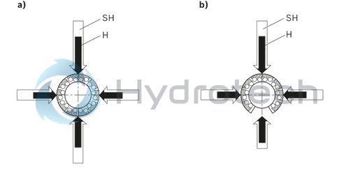
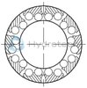
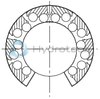
| a) | Closed |
| b) | Open |
Main direction of loading

Load direction factors
The load ratings C and C0 apply for the load direction ρ = 0°. For all other load directions, the load ratings must be multiplied by the factors fr (dynamic load rating C) or fρ0 (static load rating C0).
Load direction factor Super SH
|
Shaft |
Load direction factor (dynamic load capacity) |
|||||
|
Ø d (mm) |
⇩ |
⇒⇐ |
⇑ |
⇩ |
⇒⇐ |
⇑ |
|
20 - 25 |
1 |
0,79 |
1 |
1 |
0,79 |
0,52 |
|
30 - 60 |
1 |
0,86 |
1 |
1 |
0,86 |
0,59 |
|
Load direction factor (static load capacity) |
||||||
|
20 - 25 |
1 |
0,68 |
1 |
1 |
0,68 |
0,50 |
|
30 - 60 |
1 |
0,83 |
1 |
1 |
0,83 |
0,55 |
|
|
|||||
Reduced load capacity with short stroke
In case of short stroke, the service life of the shaft is less than that of the super Linear Bushing. The load ratings C specified in the tables must therefore be multiplied by the factor f.s .
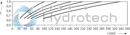
| 1) | fs = factor |
| 2) | s = movement path |
Reduced load capacity with high load
The load rating is reduced under high load F. The dynamic load rating must be multiplied by the load factor f.F .
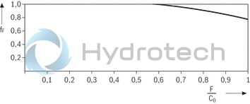
| 1) | fF = load factor |
Definition of dynamic load ratings
Tolerances and guide parallelism in operation for R1703 and R1704 Linear Sets and steel shaft with ready-mounted R1014 shaft support rail

| 1) | See "Tolerances" table for exact values. |
| 2) | P1 = parallelism P1 |
| 3) | L = guide length |
| a) | Single or combined shaft support rails |
Dimensioned drawing for tolerances and guide parallelism during operation for R1703 and R1704 Linear Sets and steel shaft with ready-mounted R1014 shaft support rail

Tolerances and guide parallelism in operation for R1703 and R1704 Linear Sets and steel shaft with ready-mounted R1016 shaft support rail

| 1) | See "Tolerances" table for exact values. |
| 2) | Shaft support rail consists of multiple parts of same type. |
| 3) | P1 = parallelism P1 |
| 4) | P2 = parallelism P2 |
| 5) | L = guide length |
| a) | Single shaft support rail |
| b) | Combined shaft support rails |
Dimensioned drawing for tolerances and guide parallelism during operation for R1703 and R1704 Linear Sets and steel shaft with ready-mounted R1016 shaft support rail

Tolerances and guide parallelism during operation for R1703 and R1704 Linear Sets and steel shaft with ready-mounted R1016 shaft support rail
|
|
Tolerance zone of the shaft |
Shaft Ød (mm) |
|||||
|
20 |
25 |
30 |
40 |
50 |
|||
|
Tolerances (µm) 3) |
H01) Multiple shaft support rails |
h6 |
+28 |
+28 |
+28 |
+28 |
+28 |
|
-69 |
-69 |
-69 |
-72 |
-72 |
|||
|
h7 |
+28 |
+28 |
+28 |
+28 |
+28 |
||
|
-77 |
-77 |
-77 |
-81 |
-81 |
|||
|
H01) Single shaft support rail |
h6 |
57 |
57 |
57 |
60 |
60 |
|
|
h7 |
65 |
65 |
65 |
67 |
69 |
||
|
Parallelism P1 2) Combined shaft support rails |
h6 |
30 |
30 |
30 |
32 |
32 |
|
|
h7 |
32 |
32 |
32 |
35 |
35 |
||
|
Parallelism P1 2) Single shaft support rail |
h6 |
20 |
20 |
20 |
22 |
22 |
|
|
h7 |
22 |
22 |
22 |
25 |
25 |
||
|
Parallelism P2 2) Combined shaft support rails |
h6 |
45 |
45 |
45 |
46 |
46 |
|
|
h7 |
46 |
46 |
46 |
48 |
48 |
||
|
Parallelism P2 2) Combined shaft support rails |
h6 |
15 |
15 |
15 |
16 |
16 |
|
|
h7 |
16 |
16 |
16 |
18 |
18 |
||
|
A31) |
h6 |
+30 |
+30 |
+30 |
+30 |
+30 |
|
|
-37 |
-37 |
-37 |
-38 |
-38 |
|||
|
h7 |
+30 |
+30 |
+30 |
+30 |
+30 |
||
|
-41 |
-41 |
-41 |
-43 |
-43 |
|||
| 1) | Measured from center of housing. |
| 2) | With clamped and fastened guide. |
| 3) | The tolerances apply for the set with shaft and shaft support rail. |
| 4) | Single or combined shaft support rails |
Load direction factors
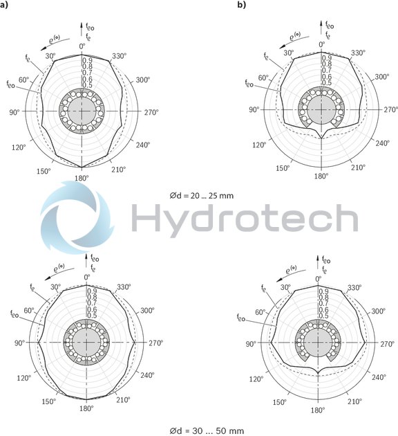
| a) | Closed |
| b) | Open |
Super Linear Bushings can be installed in any location. Choose a location that ensures that the main direction of loading is always ρ = 0°.

| a) | Lubricating hole sealed with plastic cap |
| a) | Lubricating hole sealed with plastic cap |
Dimensions
|
Ød |
mm |
20 | 25 | 30 | 40 | 50 |
|
D |
mm |
32 | 40 | 47 | 62 | 75 |
|
α |
° |
54 | 55 | 60 | 52 | |
|
A |
mm |
60 | 78 | 87 | 108 | 132 |
|
E1 |
45 mm ±0.15 | 60 mm ±0.15 | 68 mm ±0.15 | 86 mm ±0.15 | 108 mm ±0.2 | |
|
E2 |
32 mm ±0.15 | 40 mm ±0.15 | 45 mm ±0.15 | 58 mm ±0.15 | 50 mm ±0.2 | |
|
E3 |
mm |
50 | 64 | 72 | 90 | 108 |
|
E4 |
mm |
15 | 17 | 20 | 25 | 85 |
|
H |
mm |
25 | 30 | 35 | 45 | 50 |
|
Tolerance for H 1) |
µm |
+ 8 - 16 |
||||
|
H1 |
mm |
42 | 51 | 60 | 77 | 88 |
|
H3 |
mm |
10 | 11.5 | 14 | 12.5 | |
|
H4 |
mm |
3.5 | 4 | 6 | ||
|
L |
mm |
46 | 59 | 69 | 81 | 101 |
|
L3 |
mm |
16 | 21 | 26 | 30 | 39 |
|
M 1) |
30 mm ±0.01 | 39 mm ±0.01 | 43.5 mm ±0.01 | 54 mm ±0.01 | 66 mm ±0.01 | |
|
N1 |
mm |
24 | 29 | 34 | 44 | 49 |
|
N2 |
mm |
18 | 22 | 26 | 34 | |
|
S |
mm |
6.6 | 8.4 | 10.5 | 13.5 | |
|
S1 |
M8 | M10 | M12 | M16 | ||
|
S2 |
mm |
5 | 6 | 8 | 10 | |
|
SW |
mm |
2.5 | 3 | 4 | 5 | |
|
V |
mm |
5 | 6.5 | 8 | 10 | 12 |
|
W |
mm |
9.5 | 12 | 12.8 | 16.8 | 22.1 |
| 1) | Clamped (fastened) in relation to Ø d. |
Legend
|
Symbol |
Description |
Unit |
|
Ød |
Shaft diameters |
mm |
|
C/C0 |
Main direction of loading |
Legend
|
Symbol |
Description |
Unit |
|
Ød |
Shaft diameters |
mm |
|
C/C0 |
Main direction of loading |
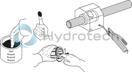
Linear sets with Super SH Linear Bushings do not come with initial lubrication. Grease the Linear Bushings before use. Service life data is based on initial lubrication and relubricated Linear Bushings.
Hydraulic-type lube nipple according to DIN 71412 Form A
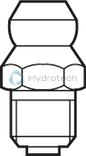
Hydraulic-type lube nipple according to DIN 71412 Form A
Catalog
Instructions
Service
Funnel-type lube nipple according to DIN 3405 Form A
Funnel-type lube nipple according to DIN 3405 Form A
Catalog
Instructions
Service
Locating screws for super linear bushings H and SH

Locating screws for super linear bushings H and SH
For securing Super Linear Bushing H and SHCatalog
Instructions
Service