


BOSCH REXROTH
R161954021
$6,147.58 USD
- BOSCH REXROTH
- Material:R161954021
- Model:KBH-5505-AS1A
Quantity in stock: 0
The Bosch Rexroth BRAKING ELEMENT KBH 5505 AS1A (R161954021) is a robust hydraulic braking unit designed for high reliability and performance in clamping and braking applications for profiled rail systems. This heavy-duty component is engineered to fit all SNS ball guide rails, ensuring compatibility across a wide range of linear motion systems. The KBH 5505 AS1A boasts an impressive service life, capable of up to 2 million clamping cycles and up to 250,000 emergency braking operations. Featuring a solid, rigid steel housing that is chemically nickel-plated, the unit offers high durability and corrosion resistance. Its integrated all-around sealing provides protection against contaminants, while the special pressure diaphragm technology ensures maximum functional reliability without pressure losses or leakage. The brake shoes come with integrated positive-locking contact profiles that deliver maximum axial rigidity when engaged. The KBH 5505 AS1A operates using hydraulic pressure of up to 240 bar for clamping and braking with precision. Decompression is achieved swiftly thanks to a pre-tensioned return spring which facilitates short decompression cycles. With its compact design conforming to DIN standards, it can be easily integrated into existing systems. This model also features threaded connections on both sides for the hydraulic connection, making installation straightforward. It has been designed with high positioning accuracy in mind and can release at a pressure of just 50 bar. The KBH 5505 AS1A can operate within a permissible ambient temperature range from -30°C to +80°C, ensuring reliable performance in various working environments. Overall, the Bosch Rexroth BRAKING ELEMENT KBH 5505 AS1A (R161954021) is an essential component for users seeking a dependable solution for precise control in their linear motion applications.
Hydraulic braking unit KBH, 55
Hydraulic braking unit KBH, FLS for ball rail systems
Size = 55
Can be used on all SNS ball guide rails
Unpacked Weight: 8.475 kg
Functional principle
Hydraulic pressure: 50 - 150 bar
Clamps and brakes with pressure
The large-scale clamping profiles are pressed directly by the hydraulic oil onto the flanks of the Ball Guide Rail via a piston principle.
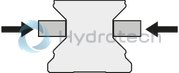
Hydraulic pressure: 0 bar
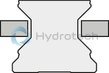
Decompression with spring force
A pre-tensioned return spring allows for short decompression cycles.
| Can be used on all SNS ball guide rails |
| Integrated all-round sealing |
| Heavy-duty brake |
| Compact design, compatible with DIN 645 |
| Clamps and brakes with pressure |
| Can be used on all SNS ball guide rails |
| Up to 1 million clamping cycles |
| Up to 2,000 emergency braking operations |
| Threaded on both sides for the hydraulic connection |
| Solid, rigid steel housing, chemically nickel-plated |
| High positioning accuracy |
| Release pressure 150 bar |
| Integrated all-round sealing |
| Special pressure diaphragm technology for maximum functional reliability without pressure losses or leakage |
| Brake shoes with integrated positive-locking, large-surface contact profiles for maximum axial rigidity |
| Super heavy-duty model |
| Low displacement |
| 10 million clamping cycles (B10d value) |
| 3D CAD | Download 3D CAD |
| 3D CAD | Download 3D CAD |
| Manual | Download Manual |
| Manual | Download Manual |
| Manual | Download Manual |
| Manual | Download Manual |
| Manual | Download Manual |
| Manual | Download Manual |
| Manual | Download Manual |
| Manual | Download Manual |
| Manual | Download Manual |
| Manual | Download Manual |
| Displacement footnote | 클램핑당 |
| Size B1 (profiled rail systems) | 184 |
| Size H (profiled rail system) | 70 |
| Holding force | 13700 |
| Height of runner block | 57 |
| Max. holding force | 13700 |
| Productgroup ID | 17 |
| Size E3 (profiled rail systems) | 70 |
| Size F | 16 |
| Size E2 (profiled rail systems) | 95 |
| Permissible ambient temperature (max) | |
| Permissible ambient temperature | 0 °C ... +70 °C |
| Displacement | 2.4 |
| Max. hydraulic operating pressure: | 150 |
| Size A (profiled rail systems) | 140 |
| Footnote 1 holding force | The inspection is done in a mounted state with a lubricated layer (ISO-VG 68). |
| Permissible ambient temperature (min) | |
| Size S1 (profiled rail systems) | 12.5 |
| Width of runner block | 140 |
| Holding force footnote 3 | At 150 bar |
| Size N2 (profiled rail systems) | 13.5 |
| Height of runner block with guide rail | 70 |
| Linear guide type | Accessories for profiled rail systems |
| Type clamping and braking units | Hydraulic |
| Size N1 (profiled rail systems) | 18 |
| Size E1 (profiled rail systems) | 116 |
| Accessories for profiled rail systems | Clamping and braking units |
| Size S2 thread diameter (profiled rail systems) | M14 |
| Weight | 8.475 |
| Size H1 (profiled rail systems) | 57 |
| Nominal size | 55 |
General technical data
|
Size |
25 | 35 | 45 | 55 | 65 | |
|
Holding force 1) |
N |
2200 2) | 5700 3) | 9900 3) | 13700 3) | 22700 3) |
|
Displacement 4) |
cm³ |
0.6 | 1.1 | 1.8 | 2.4 | 3.8 |
|
Max. hydraulic operating pressure |
bar |
100 | 150 | |||
|
Mass |
kg |
1.1 | 2.69 | 5.2 | 8.4 | 17.3 |
|
Operating conditions |
||||||
|
Size |
25 | 35 | 45 | 55 | 65 | |
|
Permissible ambient temperature (min ... max) |
0 °C ... +70 °C | |||||
| 1) | The inspection is done in a mounted state with a lubricated layer (ISO-VG 68). |
| 2) | At 100 bar |
| 3) | At 150 bar |
| 4) | Per clamping |
Clamping
during assembly work and standstill of the machine with energy at KBH of heavy handling systems clamping of machine tables from heavily machined machining centersBraking
support as brake for linear motors of heavy handling systems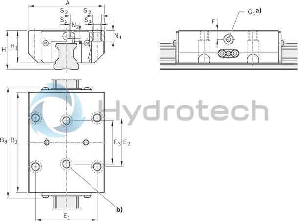
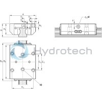
| a) | Hydraulic connection*) G1 on two sides |
| b) | In addition, both middle mounting holes must be used! |
| *) Only one connection needed. | |
| All connections sealed upon delivery. |
Dimensions
|
Size |
25 | 35 | 45 | 55 | 65 | |
|
A |
mm |
70 | 100 | 120 | 140 | 170 |
|
B1 |
mm |
92 | 120.5 | 155 | 184 | 227 |
|
B3max |
mm |
102.3 | 141 | 178 | 209 | 264 |
|
E1 |
mm |
57 | 82 | 100 | 116 | 142 |
|
E2 |
mm |
45 | 62 | 80 | 95 | 110 |
|
E3 |
mm |
40 | 52 | 60 | 70 | 82 |
|
F |
mm |
8 | 12 | 15 | 16 | 20 |
|
G1 |
3 Verstellelemente |
1/8" | 1/4" | |||
|
H |
mm |
36 | 48 | 60 | 70 | 90 |
|
H1 |
mm |
29.5 | 40 | 50 | 57 | 76 |
|
N1 1) |
mm |
9 | 12 | 15 | 18 | 23 |
|
N2 2) |
mm |
7 | 10.2 | 12.4 | 13.5 | 14 |
|
S1 |
mm |
6.8 | 8.6 | 10.5 | 12.5 | 14.5 |
|
S2 |
M8 | M10 | M12 | M14 | M16 | |
| 1) | For mounting from below with ISO 4762 |
| 2) | For mounting from below with DIN 7984 |
Additional information
Hydraulic connections
The Hydraulic Clamping Units are pre-filled with HLP 46 at the factory. The hydraulic connection is attached on two sides.
One connection is suitable for the application. Take care when venting the fixed and flexible hydraulic lines, because air connections can damage the sealing elements.
Connection structure, mounting the clamping elements
To prevent detrimental effects, e.g. permanent grinding on the linear guide, the connection structure must be rigid and in accordance with its load and requirements. If the clamping elements are tilted, this can result in contact, wear and therefore damage to the linear guide.
The setting at the factory is adapted for the linear guide and may not be altered during assembly.
It is imperative to observe the mounting instructions for the clamping and braking units and the linear guides.
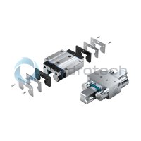
Some spring-loaded accumulators are equipped with a transport lock between the contact profiles.
This must be removed during assembly by means of pressurization of the element. When the pressure is removed, the transport lock or the associated linear guide must always lie between the contact profiles.
The clamping elements do not have any guiding function. Therefore, a runner block cannot be replaced with a clamping element. The ideal position of the clamping element is between two runner blocks.
When using several clamping elements, these should be distributed evenly on both Guide Rails in order to attain maximum rigidity for the overall construction.
Lubrication
When using the prescribed pressurizing medium, lubrication is not required.
Surface finish protection
All housings of the clamping elements are chemically nickel-plated and therefore have limited rust protection. Aluminum subsections are chemically nickel-plated according to their requirement.
B10d-value
The B10d-value specifies the number of switching cycles until 10% of components fail dangerously.