


BOSCH REXROTH
R161944031
$3,409.30 USD
- BOSCH REXROTH
- Material:R161944031
- Model:MBPS-4505-AS1A
Quantity in stock: 0
The Bosch Rexroth BRAKING ELEMENT MBPS 4505 AS1A (R161944031) is a high-performance pneumatic braking unit designed for dynamic and static stabilization in the axial direction of ball rail systems. This advanced clamping and braking unit is compatible with all SNS ball guide rails, offering versatility across multiple sizes of profiled rail systems, including B, E, H, A, and N. The MBPS 4505 AS1A ensures high positioning accuracy and provides up to 2 million clamping cycles and up to 250,000 emergency braking operations without compromising on reliability. This robust unit features an integrated all-around sealing that protects against contaminants and a mechanical gate valve gear mechanism that enables clamping and braking without pressurization due to its spring energy accumulator. In the case of a pressure drop or power loss, the device automatically clamps or brakes with spring force, ensuring safety and preventing unintended movements. The included quick-exhaust valve allows for rapid reaction times during operation changes. With its solid steel housing that is chemically nickel-plated for durability, the BRAKING ELEMENT MBPS 4505 AS1A is built to withstand harsh environments while maintaining low air consumption for efficient operation. It is maintenance-free for up to 2 million clamping cycles, further reducing downtime and operational costs. Moreover, this unit can generate holding forces up to 22,000 N at just 4 bar release pressure thanks to its design featuring three pistons connected in series combined with strong springs. It operates effectively within a temperature range of -30°C to +80°C and has an air consumption rate of approximately one liter standard air per cycle. With a nominal size of 45 mm and a weight of approximately 2 kg, it offers a compact yet powerful solution for securing components within various industrial applications requiring precise linear guidance control.
Pneumatic braking unit MBPS, 45
Pneumatic braking unit MBPS, FLS for ball rail systems
Size = 45
Can be used on all SNS ball guide rails
Unpacked Weight: 2.327 kg
Functional principle
Air pressure: 0 bar
Clamps and brakes with spring force
In the event of a pressure drop, the clamping or braking effect is achieved via a dual acting gate valve gear mechanism with one spring assembly (spring energy accumulator) in each case.
An integrated quick-exhaust valve provides for short reaction times.
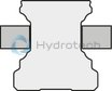
Air pressure: 4.5 - 8 bar (MBPS)
5.5 - 8 bar (UBPS)
Decompression with air pressure
The clamping profiles are held apart by the compressed air.
Free movement is possible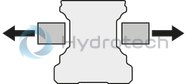
| Clamps and brakes with spring energy accumulator |
| Positive-locking integrated contact profiles ensure maximum axial and horizontal rigidity, and thus an excellent braking effect |
| Dynamic and static stabilization in the axial direction |
| Clamps and brakes without pressurization (spring energy) |
| Clamping and Braking Units in short format |
| Up to 1 million clamping cycles |
| Up to 2,000 emergency braking operations |
| Integrated all-round sealing |
| High continuous output |
| High positioning accuracy |
| Mechanical gate valve gear mechanism |
| Solid, rigid steel housing, chemically nickel-plated |
| Low air consumption |
| Maintenance-free |
| 5 million clamping cycles (B10d value) – the B10d value is not attained with the PLUS connection |
| Can be used on all SNS ball guide rails |
| Add-ons with three pistons connected in series combined with strong springs result in holding forces up to 3,800 N at just 4.5 bar release pressure |
| 3D CAD | Download 3D CAD |
| 3D CAD | Download 3D CAD |
| Manual | Download Manual |
| Manual | Download Manual |
| Manual | Download Manual |
| Manual | Download Manual |
| Manual | Download Manual |
| Manual | Download Manual |
| Manual | Download Manual |
| Manual | Download Manual |
| Manual | Download Manual |
| Manual | Download Manual |
| Size B1 | 32.2 |
| Size H (profiled rail system) | 60 |
| Height of runner block | 52 |
| Air consumption (normal liter) standard air port | 0.099 |
| Productgroup ID | 17 |
| Size E3 (profiled rail systems) | 24.5 |
| Size H2 (profiled rail systems) | 35.5 |
| Height of guide rail H2 | 35.5 |
| Size A1 (profiled rail systems) | 78.8 |
| Spring energy holding force with standard air port | 3600 |
| Permissible ambient temperature (max) | |
| Permissible ambient temperature | 0 °C ... +70 °C |
| Footnote for spring energy holding force with standard air port | Holding force by spring energy at 6 bar. The inspection is done in a mounted state with a lubricated layer (ISO-VG 68). |
| Size A (profiled rail systems) | 120 |
| Size F1 | 15 |
| Size F2 | 31.1 |
| Permissible ambient temperature (min) | |
| Width of runner block | 120 |
| Size D1 | 30 |
| Size N3 (profiled rail systems) | 15 |
| Length of runner block | 49 |
| Height of runner block with guide rail | 60 |
| Linear guide type | Accessories for profiled rail systems |
| Release pressure min. | 4.5 |
| Type clamping and braking units | Pneumatic |
| Size B (profiled rail systems) | 49 |
| Size D2 | 30 |
| Max. pneumatic operating pressure: | 8 |
| Size E1 (profiled rail systems) | 26 |
| Footnote size H1 | Ball runner block .H. (...High...) Spacer plate necessary. |
| Accessories for profiled rail systems | Clamping and braking units |
| Size S2 thread diameter (profiled rail systems) | M10 |
| Weight | 2.327 |
| Size H1 (profiled rail systems) | 52 |
| Nominal size | 45 |
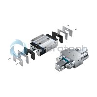

General technical data
|
Size |
20 | 25 | 30 | 35 | 45 | 55 | 65 | |
|
Spring energy holding force with standard air port 1) |
N |
750 | 1300 | 2000 | 2600 | 3800 | 4700 | |
|
Air consumption (normal liter) standard air port |
dm³/stroke |
0.034 | 0.048 | 0.065 | 0.093 | 0.099 | 0.244 | |
|
Max. pneumatic operating pressure |
bar |
8 | ||||||
|
Release pressure min. |
bar |
4.5 | ||||||
|
Mass |
kg |
0.7 | 1 | 1.8 | 1.9 | 2.3 | 3.7 | 4.2 |
|
Operating conditions |
||||||||
|
Size |
20 | 25 | 30 | 35 | 45 | 55 | 65 | |
|
Permissible ambient temperature (min ... max) |
0 °C ... +70 °C | |||||||
| 1) | Holding force by spring energy at 6 bar. The inspection is done in a mounted state with a lubricated layer (ISO-VG 68). |
Circuit1) with standard air connection
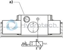
1) Holding force by spring energy at 6 bar. The inspection is done in a mounted state with a lubricated layer (ISO-VG 68)
a) Quick-exhaust valve
1 Air connection
2 Working connection
3 Exhaust
Clamping
in the event of loss of pressure during assembly work and standstill of the machine without energy of machine tables from machining centers of z-axis positioning in the resting positionBraking
in the event of energy failure in the event of a pressure drop support of the emergency stop function support as brake for linear motors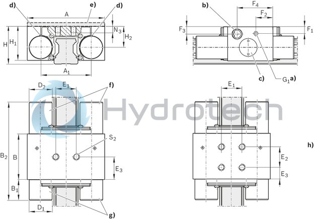
| a) | Air port*) G1 on two sides for release pressure |
| b) | Quick-exhaust on two sides |
| c) | Adjusting screw on two sides |
| d) | Exhaust on two sides |
| e) | Spacer plate (accessory) |
| f) | Piston |
| g) | Spring-loaded accumulator |
| h) | Size 55 - 65 |
| *) Only one connection needed. | |
| All connections sealed upon delivery. |
Dimensions
|
Size |
20 | 25 | 30 | 35 | 45 | 55 | 65 | |
|
A |
mm |
66 | 75 | 90 | 100 | 120 | 140 | 150 |
|
A1 |
mm |
45.7 | 49 | 58 | 68 | 78.8 | 97 | 106 |
|
B |
mm |
44 | 47 | 46 | 49 | 62 | ||
|
B1 |
mm |
19 | 20.2 | 29 | 27.7 | 32.2 | 41 | |
|
B2max |
mm |
94.5 | 95.5 | 107.5 | 106.2 | 113.7 | 145 | |
|
D1 |
mm |
16 | 22 | 25 | 28 | 30 | 39 | |
|
D2 |
mm |
18 | 22 | 25 | 28 | 30 | 39 | 38 |
|
E1 |
mm |
20 | 22 | 24 | 26 | 38 | ||
|
E2 |
mm |
- | 38 | |||||
|
E3 |
mm |
22 | 23 | 24.5 | 12 | |||
|
F1 |
mm |
5.5 | 6.5 | 7.2 | 9 | 15 | 11 | 16 |
|
F2 |
mm |
15.5 | 16.5 | 30.5 | 19 | 31.1 | 23 | |
|
F3 |
mm |
6 | 7 | 7.2 | 9.5 | 12.2 | 11 | 16 |
|
F4 |
mm |
35.5 | 34.7 | 40 | 38 | 41.6 | 40 | |
|
G1 |
3 Verstellelemente |
M5 | G1/8" | M5 | ||||
|
H |
mm |
30 | 36 | 42 | 48 | 60 | 70 | 90 |
|
H1 1) |
mm |
25.8 | 32.5 | 38.5 | 42 | 52 | 59 | 75.5 |
|
H2 |
mm |
16.2 | 20 | 24 | 26.5 | 35.5 | 38 | 53.5 |
|
N3 |
mm |
8.6 | 8 | 9 | 10 | 15 | 18 | |
|
S2 |
M6 | M8 | M10 | |||||
| 1) | Ball runner block .H. (...high...) Spacer plate necessary. |