

BOSCH REXROTH
R155244004
$887.95 USD
- BOSCH REXROTH
- Material:R155244004
- Model:SEM-E-S 40X10LX6-4
Quantity in stock: 0
The Bosch Rexroth SEM-E-S 40X10LX6-4 (R155244004) is an adjustable preload single nut designed for high precision ball screw assemblies. This meticulously engineered nut boasts a nominal diameter of 40 mm and a lead of 10 mm, accommodating left-hand thread direction for specific application requirements. It features a robust design with standard seals and standard axial clearance, ensuring reliable operation in a variety of settings. The SEM-E-S series is part of the Standard series within Bosch Rexroth's product offerings, characterized by its zero-clearance adjustable single nut configuration. The ball screw assembly is designed to handle dynamic load capacities with utmost precision, maintaining tolerance grades T3 and T5 as indicated in the product overview for screws. Users should refer to the General Technical Notes and Information for details on technical data and load capacity correction factors. This model maintains operational integrity within a temperature range of -10°C to +80°C, allowing for continuous use at temperatures up to 80°C with temporary peaks permissible up to 100°C, as measured on the outer shell of the nut. The static load rating and dynamic load capacity are optimized for these specified tolerance grades, ensuring long-term performance and reliability. The SEM-E-S 40X10LX6-4 also supports maximum permissible linear speeds detailed in the Characteristic speed section of the technical notes. Its design includes Rexroth connection dimensions with seals suitable for various applications requiring precise motion control. Weighing in at an efficient mass, this ball screw assembly component is ideal for scenarios demanding accurate positioning combined with durable construction. In summary, the Bosch Rexroth SEM-E-S 40X10LX6-4 (R155244004) stands out as a versatile and reliable component suitable for sophisticated linear motion systems that require precise control over movement and load handling capabilities.
| Rexroth connection dimensions |
| With seals |
| With left-hand version in some cases |
| Adjustable preload |
| Tolerance grade: T3 (for sizes as per the product overview for screws, see General Technical Notes and Information "Product description"), T5, T7 |
| Data Sheet | Download Data Sheet |
| 3D CAD | Download 3D CAD |
| 3D CAD | Download 3D CAD |
| Manual | Download Manual |
| Manual | Download Manual |
| Manual | Download Manual |
| Manual | Download Manual |
| Manual | Download Manual |
| Size D5 | 95 |
| Size L with tolerance | 70 mm |
| Bearing temperature max | |
| Series | Standard series |
| Bearing temperature min | |
| Nut or screw | Screw drive nut |
| Maximum operating temperature | |
| Footnote dynamic load capacity C | The load capacities are valid for tolerance grade T3 and T5 only. For other tolerance grades, please take into account the correction factor fac (see General Technical Notes and Information "Technical Data", Technical Notes). |
| Bearing temperature | -15 °C ... +80 °C |
| Category | B |
| Minimum operating temperature | |
| Size L4 | 16 |
| Size D6 | 78 |
| Size D1 f9 | 63 |
| Size D1 min | 62.931 |
| Size L3 | 25 |
| Size L10 | 22.5 |
| Size D1 max | 62.966 |
| Operating temperature | -10 °C ... +80 °C |
| Maximum permissible linear speed vmax (m/min) | 38 |
| Direction of lead | Left |
| Lead | 10 |
| Footnote static load capacity C0 | The load capacities are valid for tolerance grade T3 and T5 only. For other tolerance grades, please take into account the correction factor fac (see General Technical Notes and Information "Technical Data", Technical Notes). |
| Size L5 | 22.5 |
| Static load rating C0 | 86400 |
| Note: Maximum permissible speed vmax | See "Characteristic speed d0 • n" (section Technical notes) and "Critical speed ncr" (section Calculation and examples) |
| Nut type | SEM-E-S zero-clearance adjustable single nut |
| Productgroup ID | 17 |
| Screw drive version (drive type) | Ball screw assembly |
| Size D7 | 9 |
| Angle φ | 57 |
| Hole pattern | BB7 |
| Size Sx | 5 |
| Footnote permissible operating temperature (min...max) | Ball screw assemblies permit operation at continuous temperatures of up to 80 °C with temporary peaks of 100 °C, measurements taken on the outer shell of the nut in each case. |
| Dynamic load capacity C | 60000 |
| Size d1 | 38 |
| Size L | 70 |
| Size d2 | 33.8 |
| Footnote operating temperature max. | Ball screw assemblies permit operation at continuous temperatures of up to 80°C with temporary peaks of 100°C, measurements taken on the outer shell of the nut in each case. |
| Weight | 1.783 |
| Nominal size | 40 x 10L x 6 - 4 |
Technical data for nuts
|
Size |
C |
C0 |
vmax |
Mass |
|
d0 x P x Dw - i |
N |
N |
m/min |
kg |
| 16 x 5R x 3 - 4 | 14800 1) | 16100 1) | 30 2) | 0.24 |
| 16 x 10R x 3 - 3 | 11500 1) | 12300 1) | 60 2) | 0.25 |
| 16 x 16R x 3 - 2 | 7560 1) | 7600 1) | 96 2) | 0.42 |
| 20 x 5R x 3 - 4 | 17200 1) | 21500 1) | 30 2) | 0.31 |
| 20 x 20R x 3,5 - 2 | 10900 1) | 12100 1) | 120 2) | 0.63 |
| 25 x 5R x 3 - 4 | 19100 1) | 27200 1) | 30 2) | 0.44 |
| 25 x 10R x 3 - 4 | 18800 1) | 27000 1) | 60 2) | 0.53 |
| 25 x 25R x 3,5 - 2 | 12100 1) | 15100 1) | 150 2) | 1.13 |
| 32 x 5R x 3,5 - 4 | 25900 1) | 40000 1) | 23 2) | 0.64 |
| 32 x 10R x 3,969 - 5 | 38000 1) | 58300 1) | 47 2) | 0.87 |
| 32 x 20R x 3,969 - 2 | 16200 1) | 21800 1) | 94 2) | 1.14 |
| 32 x 32R x 3,969 - 2 | 16100 1) | 22000 1) | 150 2) | 1.44 |
| 40 x 5R x 3,5 - 5 | 34900 1) | 64100 1) | 19 2) | 0.87 |
| 40 x 10R x 6 - 4 | 60000 1) | 86400 1) | 38 2) | 1.53 |
| 40 x 20R x 6 - 3 | 45500 1) | 62800 1) | 75 2) | 1.77 |
| 40 x 40R x 6 - 2 | 30600 1) | 40300 1) | 150 2) | 3.77 |
| 50 x 5R x 3,5 - 5 | 38400 1) | 81300 1) | 15 2) | 1.23 |
| 50 x 10R x 6 - 6 | 95600 1) | 166500 1) | 30 2) | 2.44 |
| 50 x 20R x 6,5 - 3 | 57500 1) | 87900 1) | 60 2) | 3.94 |
| 50 x 40R x 6,5 - 2 | 38500 1) | 55800 1) | 120 2) | 4.42 |
| 63 x 10R x 6 - 6 | 106600 1) | 214300 1) | 24 2) | 2.94 |
| 63 x 20R x 6,5 - 3 | 63800 1) | 112100 1) | 48 2) | 4.45 |
| 63 x 40R x 6,5 - 2 | 44300 1) | 74300 1) | 95 2) | 4.95 |
| 80 x 10R x 6,5 - 6 | 130100 1) | 291700 1) | 19 2) | 4.2 |
| 80 x 20R x 12,7 - 6 | 315200 1) | 534200 1) | 30 2) | 13.3 |
| 16 x 5L x 3 - 4 | 14800 1) | 16100 1) | 0.24 | |
| 20 x 5L x 3 - 4 | 17200 1) | 21500 1) | 0.31 | |
| 25 x 5L x 3 - 4 | 19100 1) | 27200 1) | 0.44 | |
| 32 x 5L x 3,5 - 4 | 25900 1) | 40000 1) | 23 2) | 0.64 |
| 40 x 5L x 3,5 - 5 | 34900 1) | 64100 1) | 19 2) | 0.87 |
| 40 x 10L x 6 - 4 | 60000 1) | 86400 1) | 38 2) | 1.53 |
| 1) | The load ratings are valid for tolerance grades T3 and T5 only. For other tolerance grades, please take into account the correction factor fac (see General Technical Notes and Information "Technical Data", Technical Notes). |
| 2) | See "characteristic speed d0 • n" (section Technical notes) and "critical speed n"cr" (section Calculation and examples) |
Operating conditions
|
Size |
Admissible operating temperature (min ... max) 1) |
Admissible storage temperature (min ... max) |
|
d0 x P x Dw - i |
||
| 16 x 5R x 3 - 4 | -10 °C ... +80 °C | -15 °C ... +80 °C |
| 16 x 10R x 3 - 3 | ||
| 16 x 16R x 3 - 2 | ||
| 20 x 5R x 3 - 4 | ||
| 20 x 20R x 3,5 - 2 | ||
| 25 x 5R x 3 - 4 | ||
| 25 x 10R x 3 - 4 | ||
| 25 x 25R x 3,5 - 2 | ||
| 32 x 5R x 3,5 - 4 | ||
| 32 x 10R x 3,969 - 5 | ||
| 32 x 20R x 3,969 - 2 | ||
| 32 x 32R x 3,969 - 2 | ||
| 40 x 5R x 3,5 - 5 | ||
| 40 x 10R x 6 - 4 | ||
| 40 x 20R x 6 - 3 | ||
| 40 x 40R x 6 - 2 | ||
| 50 x 5R x 3,5 - 5 | ||
| 50 x 10R x 6 - 6 | ||
| 50 x 20R x 6,5 - 3 | ||
| 50 x 40R x 6,5 - 2 | ||
| 63 x 10R x 6 - 6 | ||
| 63 x 20R x 6,5 - 3 | ||
| 63 x 40R x 6,5 - 2 | ||
| 80 x 10R x 6,5 - 6 | ||
| 80 x 20R x 12,7 - 6 | ||
| 16 x 5L x 3 - 4 | ||
| 20 x 5L x 3 - 4 | ||
| 25 x 5L x 3 - 4 | ||
| 32 x 5L x 3,5 - 4 | ||
| 40 x 5L x 3,5 - 5 | ||
| 40 x 10L x 6 - 4 |
| 1) | Ball screw assemblies are suitable for continuous operation at temperatures up to 80 °C with temporary peaks of 100 °C (measurements taken on the outer shell of the nut). |
Legend
|
Symbol |
Description |
Unit |
|
d0 |
Nominal diameter |
mm |
|
P |
Lead (R = right-hand, L = left-hand) |
|
|
Dw |
Ball diameter |
mm |
|
i |
Number of ball track turns |
|
|
C |
Dynamic load capacity |
N |
|
C0 |
Static load capacity |
N |
|
vmax |
Maximum permissible speed |
m/min |
Technical notes
| 1) | Lube port at flange center (lube port machining: Flat surface L3 ≤ 15 mm, countersink L3 > 15 mm; for size 8 x 2.5 a DIN 3405 funnel-type lube nipple is provided.) |
| 2) | right |
| 3) | left |
| 4) | Nut rework: Axial lube port |
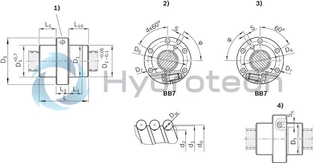
Dimensions
|
Size |
D1 min |
D1 max |
d1 |
d2 |
D1 |
D5 |
Hole pattern |
D6 |
D7 |
L |
L3 |
L4 |
L5 |
L10 |
S 1) |
Sx |
φ |
|
d0 x P x Dw - i |
f9 |
||||||||||||||||
|
mm |
mm |
mm |
mm |
mm |
mm |
mm |
mm |
mm |
mm |
mm |
mm |
mm |
mm |
mm |
° |
||
| 16 x 5R x 3 - 4 | 27.94 | 27.975 | 15 | 12.9 | 28 | 53 | BB7 | 40 | 6.6 | 38 | 15 | 10 | 11.5 | 11.5 | M6 | 4 | 53 |
| 16 x 10R x 3 - 3 | 45 | 15 | 15 | 15 | 180 | ||||||||||||
| 16 x 16R x 3 - 2 | 32.945 | 32.973 | 33 | 58 | 45 | 50 | |||||||||||
| 20 x 5R x 3 - 4 | 32.935 | 32.97 | 19 | 16.9 | 40 | 10 | 12.5 | 12.5 | 56 | ||||||||
| 20 x 20R x 3,5 - 2 | 37.945 | 37.973 | 16.7 | 38 | 63 | 50 | 57 | 20 | 18.5 | 18.5 | 18.5 | 60 | |||||
| 25 x 5R x 3 - 4 | 37.935 | 37.97 | 24 | 21.9 | 45 | 10 | 12.5 | 12.5 | |||||||||
| 25 x 10R x 3 - 4 | 64 | 16 | 22 | 22 | |||||||||||||
| 25 x 25R x 3,5 - 2 | 47.945 | 47.973 | 21.4 | 48 | 73 | 60 | 70 | 25 | 22.5 | 22.5 | 22.5 | 48 | |||||
| 32 x 5R x 3,5 - 4 | 47.935 | 47.97 | 31 | 28.4 | 48 | 20 | 10 | 14 | 14 | 60 | |||||||
| 32 x 10R x 3,969 - 5 | 27.9 | 77 | 16 | 28.5 | 28.5 | 168 | |||||||||||
| 32 x 20R x 3,969 - 2 | 55.941 | 55.969 | 56 | 80 | 68 | 64 | 22 | 22 | 22 | 60 | |||||||
| 32 x 32R x 3,969 - 2 | 88 | 34 | 34 | 34 | |||||||||||||
| 40 x 5R x 3,5 - 5 | 55.931 | 55.966 | 39 | 36.4 | 54 | 10 | 17 | 17 | M8x1 | 5 | 65 | ||||||
| 40 x 10R x 6 - 4 | 62.931 | 62.966 | 38 | 33.8 | 63 | 95 | 78 | 9 | 70 | 25 | 16 | 22.5 | 22.5 | 57 | |||
| 40 x 20R x 6 - 3 | 62.941 | 62.969 | 88 | 25 | 31.5 | 31.5 | 180 | ||||||||||
| 40 x 40R x 6 - 2 | 71.941 | 71.969 | 72 | 110 | 90 | 11 | 102 | 40 | 31 | 31 | 31 | 49 | |||||
| 50 x 5R x 3,5 - 5 | 67.931 | 67.966 | 49 | 46.4 | 68 | 98 | 82 | 9 | 54 | 25 | 10 | 14.5 | 14.5 | 67 | |||
| 50 x 10R x 6 - 6 | 71.931 | 71.966 | 48 | 43.8 | 72 | 110 | 90 | 11 | 90 | 30 | 16 | 30 | 30 | 61 | |||
| 50 x 20R x 6,5 - 3 | 84.936 | 84.964 | 43.3 | 85 | 125 | 105 | 92 | 25 | 31 | 31 | 180 | ||||||
| 50 x 40R x 6,5 - 2 | 109 | 39.5 | 39.5 | 39.5 | 60 | ||||||||||||
| 63 x 10R x 6 - 6 | 84.926 | 84.961 | 61 | 56.8 | 90 | 16 | 30 | 30 | 65 | ||||||||
| 63 x 20R x 6,5 - 3 | 94.936 | 94.964 | 56.3 | 95 | 140 | 118 | 14 | 92 | 25 | 31 | 31 | 190 | |||||
| 63 x 40R x 6,5 - 2 | 109 | 39.5 | 39.5 | 39.5 | 70 | ||||||||||||
| 80 x 10R x 6,5 - 6 | 104.926 | 104.961 | 78 | 73.3 | 105 | 150 | 125 | 95 | 16 | 32.5 | 32.5 | 67 | |||||
| 80 x 20R x 12,7 - 6 | 124.931 | 124.959 | 76 | 67 | 125 | 180 | 152 | 18 | 170 | 50 | 25 | 60 | 60 | 60 | |||
| 16 x 5L x 3 - 4 | 27.94 | 27.975 | 15 | 12.9 | 28 | 53 | 40 | 6.6 | 38 | 15 | 10 | 11.5 | 11.5 | M6 | 53 | ||
| 20 x 5L x 3 - 4 | 32.935 | 32.97 | 19 | 16.9 | 33 | 58 | 45 | 40 | 12.5 | 12.5 | 56 | ||||||
| 25 x 5L x 3 - 4 | 37.935 | 37.97 | 24 | 21.9 | 38 | 63 | 50 | 45 | 20 | 60 | |||||||
| 32 x 5L x 3,5 - 4 | 47.935 | 47.97 | 31 | 28.4 | 48 | 73 | 60 | 48 | 14 | 14 | 59 | ||||||
| 40 x 5L x 3,5 - 5 | 55.931 | 55.966 | 39 | 36.4 | 56 | 80 | 68 | 54 | 17 | 17 | M8x1 | 65 | |||||
| 40 x 10L x 6 - 4 | 62.931 | 62.966 | 38 | 33.8 | 63 | 95 | 78 | 9 | 70 | 25 | 16 | 22.5 | 22.5 | 57 |
| 1) | Lube port machining: Flat surface L3 ≤ 15 mm, countersink L3 > 15 mm; for size 8 x 2.5 a DIN 3405 funnel-type lube nipple is provided. |
Legend
|
Symbol |
Description |
|
d0 |
Nominal diameter |
|
P |
Lead (R = right-hand, L = left-hand) |
|
Dw |
Ball diameter |
|
i |
Number of ball track turns |
Attention: When setting up applications, do not allow components to collide with the front lube unit.
Nut housing MGS
Nut housing MGS
Steel nut housings MGS are designed for FEM-E-S, FDM-E-S, FEP-E-S and SEM-E-S nuts.Catalog
Service
CAD data
Front lube unit – ball screw assembly

Front lube unit – ball screw assembly
Catalog
Service
Arrestor nut

Arrestor nut
Catalog
Service
Required and supplementary documentation
For further instructions and information, please refer to the documentation for this product.
You can find PDF files of these documents on the Internet at www.boschrexroth.com/mediadirectory.
If you are unsure about using this product, please contact Bosch Rexroth.
Notes