

BOSCH REXROTH
R153249013
$341.84 USD
- BOSCH REXROTH
- Material:R153249013
- Model:FEM-E-S12X10RX2-2
Quantity in stock: 0
The Bosch Rexroth FEM-E-S 12X10RX2-2 (R153249013) is a high-precision ball screw assembly designed for linear motion applications. This single nut with flange from the Miniature series is engineered to provide smooth and accurate movement in a compact form factor. The product features a nominal diameter of 12mm and a lead of 10mm, which determines the travel distance per revolution of the screw. It is equipped with standard seals and comes with a standard axial clearance to ensure optimal performance. The FEM-E-S 12X10RX2-2 nut is designed with Rexroth connection dimensions for seamless integration into various systems. It has been manufactured to tolerance grade T, ensuring high precision and consistency in motion control tasks. The ball screw assembly can operate within a temperature range of -10°C to +80°C, allowing for use in diverse environments. For applications requiring higher temperatures, it can withstand temporary peaks up to 100°C. With its dynamic load capacity C and static load rating C, this product is capable of handling significant loads while maintaining its efficiency and longevity. The maximum permissible linear speed (vmax) ensures that the assembly can support rapid movements without compromising on stability or accuracy. This Bosch Rexroth ball screw nut is particularly suitable for applications where space is limited but precise linear motion is required. Its robust design, combined with the reliability associated with Bosch Rexroth's engineering standards, makes it an excellent choice for industries that demand precision and durability in their motion control solutions. The weight and dimensions of this product are optimized for ease of installation and compatibility with numerous design requirements, making it a versatile component for various mechanical assemblies.
| Rexroth connection dimensions |
| With seals |
| Preload class: C0, C00, C1 |
| Tolerance grade: T5, T7, T9 |
| Rexroth connecting dimensions: Rexroth mounting dimensions |
| With seals |
| Data Sheet | Download Data Sheet |
| 3D CAD | Download 3D CAD |
| 3D CAD | Download 3D CAD |
| Manual | Download Manual |
| Manual | Download Manual |
| Manual | Download Manual |
| Manual | Download Manual |
| Manual | Download Manual |
| Size D5 | 40 |
| Size L with tolerance | 33 mm |
| Bearing temperature max | |
| Nut type | FEM-E-S single nut with flange |
| Series | Miniature series |
| Bearing temperature min | |
| Productgroup ID | 17 |
| Nut or screw | Screw drive nut |
| Screw drive version (drive type) | Ball screw assembly |
| Maximum operating temperature | |
| Footnote dynamic load capacity C | The load capacities are valid for tolerance grade T5 only. For other tolerance grades, please take into account the correction factor fac (see General Technical Notes and Information "Technical Data", Technical Notes). |
| Bearing temperature | -15 °C ... +80 °C |
| Category | B |
| Minimum operating temperature | |
| Size L4 | 16 |
| Size D6 | 32 |
| Size L3 | 12 |
| Size D7 | 4.5 |
| Size L10 | 21 |
| Operating temperature | -10 °C ... +80 °C |
| Maximum permissible linear speed vmax (m/min) | 60 |
| Angle φ | 330 |
| Direction of lead | Right |
| Lead | 10 |
| Footnote static load capacity C0 | The load capacities are valid for tolerance grade T5 only. For other tolerance grades, please take into account the correction factor fac (see General Technical Notes and Information "Technical Data", Technical Notes). |
| Static load rating C0 | 3600 |
| Size Sx | 4 |
| Footnote permissible operating temperature (min...max) | Ball screw assemblies permit operation at continuous temperatures of up to 80 °C with temporary peaks of 100 °C, measurements taken on the outer shell of the nut in each case. |
| Size D1 g6 | 24 |
| Dynamic load capacity C | 3000 |
| Size d1 | 11.4 |
| Size L | 33 |
| Size d2 | 9.9 |
| Footnote operating temperature max. | Ball screw assemblies permit operation at continuous temperatures of up to 80°C with temporary peaks of 100°C, measurements taken on the outer shell of the nut in each case. |
| Note: Maximum permissible speed vmax | See "Characteristic speed d0 • n" (see General Technical Notes and Information, "Technical Data" (Technical Notes), and "Critical speed ncr" (see General Technical Notes and Information, "Project planning notes") |
| Weight | 0.194 |
| Nominal size | 12 x 10R x 2 - 2 |

Technical data for nuts
|
Size |
C |
C0 |
vmax |
Mass |
|
d0 x P x Dw - i |
N |
N |
m/min |
kg |
| 8 x 2,5R x 1,588 - 3 | 2640 1) | 2800 1) | 15 2) | 0.05 |
| 12 x 5R x 2 - 3 | 4560 1) | 5800 1) | 30 2) | 0.12 |
| 12 x 10R x 2 - 2 | 3000 1) | 3600 1) | 60 2) | 0.14 |
| 1) | The load ratings are valid for tolerance grade T5 only. For other tolerance grades, please take into account the correction factor fac (see general technical notes and information, “Technical Data”, (technical notes). |
| 2) | See "characteristic speed d0 • n" (see General Technical Notes and Information "Technical Data" (Technical Notes), and "Critical Speed ncr" (see General Technical Notes and Information, "Project planning notes") |
Operating conditions
|
Size |
Admissible operating temperature (min ... max) 1) |
Admissible storage temperature (min ... max) |
|
d0 x P x Dw - i |
||
| 8 x 2,5R x 1,588 - 3 | -10 °C ... +80 °C | -15 °C ... +80 °C |
| 12 x 5R x 2 - 3 | ||
| 12 x 10R x 2 - 2 |
| 1) | Ball screw assemblies are suitable for continuous operation at temperatures up to 80 °C with temporary peaks of 100 °C (measurements taken on the outer shell of the nut). |
Legend
|
Symbol |
Description |
Unit |
|
d0 |
Nominal diameter |
mm |
|
P |
Lead (R = right-hand) |
|
|
Dw |
Ball diameter |
mm |
|
i |
Number of ball track turns |
|
|
C |
Dynamic load capacity |
N |
|
C0 |
Static load capacity |
N |
|
vmax |
Maximum permissible speed |
m/min |
Technical notes
| 1) | Lube port at flange center (lube port machining: Flat surface L3 ≤ 15 mm; for size 8 x 2.5 a DIN 3405 funnel-type lube nipple is provided.) |
| 2) | Nut rework: Axial lube port |
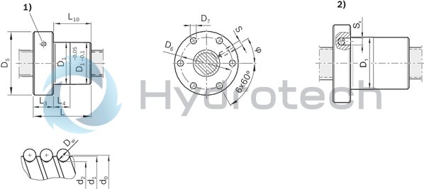
Dimensions
|
Size |
d1 |
d2 |
D1 |
D5 |
D6 |
D7 |
L |
L3 |
L4 |
L10 |
S 1) |
Sx |
φ |
|
d0 x P x Dw - i |
g6 |
||||||||||||
|
mm |
mm |
mm |
mm |
mm |
mm |
mm |
mm |
mm |
mm |
mm |
mm |
° |
|
| 8 x 2,5R x 1,588 - 3 | 7.5 | 6.3 | 16 | 30 | 23 | 3.4 | 16 | 8 | 8 | 8 | Ø4 | - | 30 |
| 12 x 5R x 2 - 3 | 11.4 | 9.9 | 24 | 40 | 32 | 4.5 | 28 | 12 | 10 | 16 | M6 | 4 | 330 |
| 12 x 10R x 2 - 2 | 33 | 16 | 21 |
| 1) | Lube port machining: Flat surface L3 ≤ 15 mm; for size 8 x 2.5 a DIN 3405 funnel-type lube nipple is provided. |
Legend
|
Symbol |
Description |
Unit |
|
d0 |
Nominal diameter |
mm |
|
P |
Lead (R = right-hand) |
|
|
Dw |
Ball diameter |
mm |
|
i |
Number of ball track turns |
Nut housing MGS
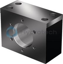
Nut housing MGS
Steel nut housings MGS are designed for FEM-E-S, FDM-E-S, FEP-E-S and SEM-E-S nuts.Catalog
Service
CAD data
Arrestor nut

Arrestor nut
Catalog
Service
Required and supplementary documentation
For further instructions and information, please refer to the documentation for this product.
You can find PDF files of these documents on the Internet at www.boschrexroth.com/mediadirectory.
If you are unsure about using this product, please contact Bosch Rexroth.
Notes