


BOSCH REXROTH
R151231012
$398.55 USD
- BOSCH REXROTH
- Material:R151231012
- Model:ZEM-E-S32X5RX3,5-4
Quantity in stock: 0
The Bosch Rexroth ZEM-E-S 32X5RX35-4 (R151231012) is a high-precision ball screw assembly designed for linear motion applications. This cylindrical single nut ZEMES is engineered with a nominal diameter of 32mm and a lead of 5mm, providing reliable and efficient movement. The unit comes with standard seals and standard axial clearance to ensure smooth operation under various conditions. Featuring a robust design, the ZEM-E-S 32X5RX35-4 incorporates multiple ball track turns and adheres to Rexroth connection dimensions for compatibility and ease of installation. It is available in preload classes C0 to C3, with a tolerance grade T ensuring precise operation. The nut type is from the ZEMES cylindrical single nut series within the Standard series product group. This ball screw assembly operates within a temperature range of -10°C to +100°C, with the capability to withstand temporary peaks up to 120°C as measured on the outer shell of the nut, ensuring durability in various working environments. The maximum permissible linear speed is denoted as vmax m/min, which caters to high-speed requirements. With its static load rating C0 and dynamic load capacity C0, this model offers reliable performance for tolerance grades T7 and T9; however, for other tolerance grades, users should consider correction factors as specified in the technical notes provided by Bosch Rexroth. The ZEM-E-S 32X5RX35-4 has an overall weight of . kg and offers a right-handed lead direction. It represents an essential component for those requiring precise linear motion control in their mechanical systems or machinery setups. Its design ensures compatibility with various applications while maintaining Bosch Rexroth's standards for quality and performance.
| Rexroth connection dimensions |
| With seals |
| With left-hand version in some cases |
| Preload class: C0, C00, C1, C2, C3 |
| Tolerance grade: T3 (for sizes as per the product overview for screws, see general technical notes and information, “Product description”), T5, T7, T9 |
| Data Sheet | Download Data Sheet |
| 3D CAD | Download 3D CAD |
| 3D CAD | Download 3D CAD |
| Manual | Download Manual |
| Manual | Download Manual |
| Manual | Download Manual |
| Manual | Download Manual |
| Manual | Download Manual |
| Size L with tolerance | 48 mm ±0,1 |
| Bearing temperature max | |
| Series | Standard series |
| Bearing temperature min | |
| Nut or screw | Screw drive nut |
| Maximum operating temperature | |
| Footnote dynamic load capacity C | The load capacities are valid for tolerance grade T3 and T5 only. For other tolerance grades, please take into account the correction factor fac (see General Technical Notes and Information "Technical Data", Technical Notes). |
| Bearing temperature | -15 °C ... +80 °C |
| Category | B |
| Size L7 | 9.5 |
| Minimum operating temperature | |
| Operating temperature | -10 °C ... +80 °C |
| Maximum permissible linear speed vmax (m/min) | 23 |
| Direction of lead | Right |
| Lead | 5 |
| Size L6 | 14 |
| Footnote static load capacity C0 | The load capacities are valid for tolerance grade T3 and T5 only. For other tolerance grades, please take into account the correction factor fac (see General Technical Notes and Information "Technical Data", Technical Notes). |
| Size B P9 | 5 |
| Static load rating C0 | 40000 |
| Size T1 | 3 |
| Size D1 g6 | 48 |
| Size D4 | 4 |
| Size L11 with tolerance | 20 mm +0,2 |
| Note: Maximum permissible speed vmax | See "Characteristic speed d0 • n" (see General Technical Notes and Information, "Technical Data" (Technical Notes), and "Critical speed ncr" (see General Technical Notes and Information, "Project planning notes") |
| Nut type | ZEM-E-S cylindrical single nut |
| Productgroup ID | 17 |
| Screw drive version (drive type) | Ball screw assembly |
| Size L11 | 20 |
| Footnote permissible operating temperature (min...max) | Ball screw assemblies permit operation at continuous temperatures of up to 80 °C with temporary peaks of 100 °C, measurements taken on the outer shell of the nut in each case. |
| Dynamic load capacity C | 25900 |
| Size d1 | 31 |
| Size L | 48 |
| Size d2 | 28.4 |
| Footnote operating temperature max. | Ball screw assemblies permit operation at continuous temperatures of up to 80°C with temporary peaks of 100°C, measurements taken on the outer shell of the nut in each case. |
| Weight | 0.440 |
| Nominal size | 32 x 5R x 3,5 - 4 |
Technical data for nuts
|
Size |
C |
C0 |
vmax |
Mass |
|
d0 x P x Dw - i |
N |
N |
m/min |
kg |
| 16 x 5R x 3 - 4 | 14800 1) | 16100 1) | 30 2) | 0.09 |
| 16 x 10R x 3 - 3 | 11500 1) | 12300 1) | 60 2) | 0.12 |
| 16 x 16R x 3 - 2 | 7560 1) | 7600 1) | 96 2) | 0.2 |
| 16 x 16R x 3 - 3 | 11200 1) | 12300 1) | 0.16 | |
| 20 x 5R x 3 - 5 | 21000 1) | 27300 1) | 30 2) | |
| 20 x 10R x 3 - 4 | 16900 1) | 21300 1) | 60 2) | |
| 20 x 20R x 3,5 - 2 | 10900 1) | 12100 1) | 120 2) | 0.34 |
| 20 x 20R x 3,5 - 3 | 16000 1) | 18800 1) | 0.37 | |
| 25 x 5R x 3 - 4 | 19100 1) | 27200 1) | 30 2) | 0.19 |
| 25 x 10R x 3 - 4 | 18800 1) | 27000 1) | 60 2) | 0.28 |
| 25 x 25R x 3,5 - 2 | 12100 1) | 15100 1) | 150 2) | 0.73 |
| 25 x 25R x 3,5 - 3 | 17600 1) | 23300 1) | 0.5 | |
| 32 x 5R x 3,5 - 4 | 25900 1) | 40000 1) | 23 2) | 0.32 |
| 32 x 10R x 3,969 - 5 | 38000 1) | 58300 1) | 47 2) | 0.5 |
| 32 x 20R x 3,969 - 2 | 16200 1) | 21800 1) | 94 2) | 0.74 |
| 32 x 20R x 3,969 - 3 | 23600 1) | 33700 1) | 0.66 | |
| 32 x 32R x 3,969 - 2 | 16100 1) | 22000 1) | 150 2) | 1.03 |
| 32 x 32R x 3,969 - 3 | 23400 1) | 34000 1) | 0.97 | |
| 40 x 5R x 3,5 - 5 | 34900 1) | 64100 1) | 19 2) | 0.44 |
| 40 x 10R x 6 - 4 | 60000 1) | 86400 1) | 38 2) | 0.88 |
| 40 x 10R x 6 - 6 | 86500 1) | 132200 1) | 1.15 | |
| 40 x 20R x 6 - 3 | 45500 1) | 62800 1) | 75 2) | 1.13 |
| 40 x 40R x 6 - 2 | 30600 1) | 40300 1) | 150 2) | 2.23 |
| 40 x 40R x 6 - 3 | 44400 1) | 62300 1) | 1.85 | |
| 50 x 5R x 3,5 - 5 | 38400 1) | 81300 1) | 15 2) | 0.62 |
| 50 x 10R x 6 - 6 | 95600 1) | 166500 1) | 30 2) | 1.34 |
| 50 x 20R x 6,5 - 3 | 57500 1) | 87900 1) | 60 2) | 2.39 |
| 63 x 10R x 6 - 6 | 106600 1) | 214300 1) | 24 2) | 1.59 |
| 80 x 10R x 6,5 - 6 | 130100 1) | 291700 1) | 19 2) | 2.23 |
| 16 x 5L x 3 - 4 | 14800 1) | 16100 1) | 30 2) | 0.09 |
| 20 x 5L x 3 - 5 | 21000 1) | 27300 1) | 0.16 | |
| 25 x 5L x 3 - 4 | 19100 1) | 27200 1) | 0.19 | |
| 32 x 5L x 3,5 - 4 | 25900 1) | 40000 1) | 23 2) | 0.32 |
| 40 x 5L x 3,5 - 5 | 34900 1) | 64100 1) | 19 2) | 0.44 |
| 40 x 10L x 6 - 4 | 60000 1) | 86400 1) | 38 2) | 0.88 |
| 1) | The load ratings are valid for tolerance grades T3 and T5 only. For other tolerance grades, please take into account the correction factor fac (see General Technical Notes and Information "Technical Data", Technical Notes). |
| 2) | See "characteristic speed d0 • n" (see General Technical Notes and Information "Technical Data" (Technical Notes), and "Critical Speed ncr" (see General Technical Notes and Information, "Project planning notes") |
Operating conditions
|
Size |
Admissible operating temperature (min ... max) 1) |
Admissible storage temperature (min ... max) |
|
d0 x P x Dw - i |
||
| 16 x 5R x 3 - 4 | -10 °C ... +80 °C | -15 °C ... +80 °C |
| 16 x 10R x 3 - 3 | ||
| 16 x 16R x 3 - 2 | ||
| 16 x 16R x 3 - 3 | ||
| 20 x 5R x 3 - 5 | ||
| 20 x 10R x 3 - 4 | ||
| 20 x 20R x 3,5 - 2 | ||
| 20 x 20R x 3,5 - 3 | ||
| 25 x 5R x 3 - 4 | ||
| 25 x 10R x 3 - 4 | ||
| 25 x 25R x 3,5 - 2 | ||
| 25 x 25R x 3,5 - 3 | ||
| 32 x 5R x 3,5 - 4 | ||
| 32 x 10R x 3,969 - 5 | ||
| 32 x 20R x 3,969 - 2 | ||
| 32 x 20R x 3,969 - 3 | ||
| 32 x 32R x 3,969 - 2 | ||
| 32 x 32R x 3,969 - 3 | ||
| 40 x 5R x 3,5 - 5 | ||
| 40 x 10R x 6 - 4 | ||
| 40 x 10R x 6 - 6 | ||
| 40 x 20R x 6 - 3 | ||
| 40 x 40R x 6 - 2 | ||
| 40 x 40R x 6 - 3 | ||
| 50 x 5R x 3,5 - 5 | ||
| 50 x 10R x 6 - 6 | ||
| 50 x 20R x 6,5 - 3 | ||
| 63 x 10R x 6 - 6 | ||
| 80 x 10R x 6,5 - 6 | ||
| 16 x 5L x 3 - 4 | ||
| 20 x 5L x 3 - 5 | ||
| 25 x 5L x 3 - 4 | ||
| 32 x 5L x 3,5 - 4 | ||
| 40 x 5L x 3,5 - 5 | ||
| 40 x 10L x 6 - 4 |
| 1) | Ball screw assemblies are suitable for continuous operation at temperatures up to 80 °C with temporary peaks of 100 °C (measurements taken on the outer shell of the nut). |
Legend
|
Symbol |
Description |
Unit |
|
d0 |
Nominal diameter |
mm |
|
P |
Lead (R = right-hand, L = left-hand) |
|
|
Dw |
Ball diameter |
mm |
|
i |
Number of ball track turns |
|
|
C |
Dynamic load capacity |
N |
|
C0 |
Static load capacity |
N |
|
vmax |
Maximum permissible speed |
m/min |
Technical notes
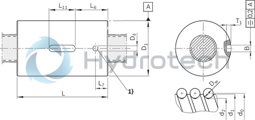
| 1) | Lube port |
Dimensions
|
Size |
d1 |
d2 |
B |
D1 |
D4 |
L |
L6 |
L7 |
L11 |
T1 |
|
P9 |
g6 |
|||||||||
|
mm |
mm |
mm |
mm |
mm |
mm |
mm |
mm |
|||
| 16 x 5R x 3 - 4 | 15 | 12.9 | 5 | 28 | 4 | 35 mm ±0.1 | 14.5 | 9.5 | 12 mm +0.2 | 3 mm +0.1 |
| 16 x 10R x 3 - 3 | 45 mm ±0.1 | 16 mm +0.2 | ||||||||
| 16 x 16R x 3 - 2 | 33 | |||||||||
| 16 x 16R x 3 - 3 | 28 | 61 mm ±0.1 | 22.5 | |||||||
| 20 x 5R x 3 - 5 | 19 | 16.9 | 33 | 45 mm ±0.1 | 14.5 | |||||
| 20 x 10R x 3 - 4 | 60 mm ±0.1 | 22 | ||||||||
| 20 x 20R x 3,5 - 2 | 16.7 | 38 | 64 mm ±0.1 | 20 mm +0.2 | ||||||
| 20 x 20R x 3,5 - 3 | 36 | 77 mm ±0.1 | 28.5 | |||||||
| 25 x 5R x 3 - 4 | 24 | 21.9 | 38 | 45 mm ±0.1 | 14.5 | 16 mm +0.2 | ||||
| 25 x 10R x 3 - 4 | 64 mm ±0.1 | 22 | 20 mm +0.2 | |||||||
| 25 x 25R x 3,5 - 2 | 21.4 | 48 | 80 mm ±0.1 | 30 | 10.5 | |||||
| 25 x 25R x 3,5 - 3 | 40 | 95 mm ±0.1 | 37.5 | |||||||
| 32 x 5R x 3,5 - 4 | 31 | 28.4 | 48 | 48 mm ±0.1 | 14 | 9.5 | ||||
| 32 x 10R x 3,969 - 5 | 27.9 | 77 mm ±0.1 | 28.5 | |||||||
| 32 x 20R x 3,969 - 2 | 56 | 64 mm ±0.1 | 22 | |||||||
| 32 x 20R x 3,969 - 3 | 50 | 84 mm ±0.1 | 32 | |||||||
| 32 x 32R x 3,969 - 2 | 56 | 88 mm ±0.1 | 34 | |||||||
| 32 x 32R x 3,969 - 3 | 50 | 120 mm ±0.1 | 50 | |||||||
| 40 x 5R x 3,5 - 5 | 39 | 36.4 | 56 | 54 mm ±0.1 | 17 | |||||
| 40 x 10R x 6 - 4 | 38 | 33.8 | 63 | 70 mm ±0.1 | 25 | 14 | ||||
| 40 x 10R x 6 - 6 | 90 mm ±0.1 | 35 | ||||||||
| 40 x 20R x 6 - 3 | 88 mm ±0.1 | 34 | ||||||||
| 40 x 40R x 6 - 2 | 72 | 113 mm ±0.1 | 46.5 | |||||||
| 40 x 40R x 6 - 3 | 63 | 142 mm ±0.1 | 61 | |||||||
| 50 x 5R x 3,5 - 5 | 49 | 46.4 | 68 | 54 mm ±0.1 | 17 | 9.5 | ||||
| 50 x 10R x 6 - 6 | 48 | 43.8 | 72 | 5 | 90 mm ±0.1 | 35 | 14 | |||
| 50 x 20R x 6,5 - 3 | 43.4 | 6 | 85 | 92 mm ±0.1 | 30 | 32 mm +0.2 | 3.5 mm +0.1 | |||
| 63 x 10R x 6 - 6 | 61 | 56.8 | 90 mm ±0.1 | 29 | ||||||
| 80 x 10R x 6,5 - 6 | 78 | 73.3 | 105 | 95 mm ±0.1 | 31.5 | 15 | ||||
| 16 x 5L x 3 - 4 | 15 | 12.9 | 5 | 28 | 4 | 35 mm ±0.1 | 14.5 | 9.5 | 12 mm +0.2 | 3 mm +0.1 |
| 20 x 5L x 3 - 5 | 19 | 16.9 | 33 | 45 mm ±0.1 | 16 mm +0.2 | |||||
| 25 x 5L x 3 - 4 | 24 | 21.9 | 38 | |||||||
| 32 x 5L x 3,5 - 4 | 31 | 28.4 | 48 | 48 mm ±0.1 | 14 | 20 mm +0.2 | ||||
| 40 x 5L x 3,5 - 5 | 39 | 36.4 | 56 | 54 mm ±0.1 | 17 | |||||
| 40 x 10L x 6 - 4 | 38 | 33.8 | 63 | 70 mm ±0.1 | 25 | 14 |
Legend
|
Symbol |
Description |
|
d0 |
Nominal diameter |
|
P |
Lead (R = right-hand, L = left-hand) |
|
Dw |
Ball diameter |
|
i |
Number of ball track turns |
Nut housing MGA
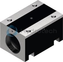
Nut housing MGA
Aluminum nut housings MGA are designed for ZEM-E-S, ZEM-E-K and ZEM-E-A nutsCatalog
Service
CAD data
Threaded Rings GWR
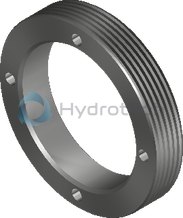
Threaded Rings GWR
For angular-contact thrust ball bearing LGNCatalog
Service
CAD data
Arrestor nut

Arrestor nut
Catalog
Service
Required and supplementary documentation
For further instructions and information, please refer to the documentation for this product.
You can find PDF files of these documents on the Internet at www.boschrexroth.com/mediadirectory.
If you are unsure about using this product, please contact Bosch Rexroth.
Notes