

BOSCH REXROTH
R151217014
$688.91 USD
- BOSCH REXROTH
- Material:R151217014
- Model:SEM-E-S 20X20RX3,5-2
Quantity in stock: 0
The Bosch Rexroth SEM-E-S 20X20RX35-2 (R151217014) is an adjustable preload single nut designed for high-precision ball screw assemblies. It is part of the Standard series and features a nominal diameter of 20 mm with a lead of right-hand direction. The SEM-E-S 20X20RX35-2 is engineered with Rexroth connection dimensions, incorporating seals and offering the possibility of a left-hand version in certain applications. This nut type falls under the SEMES zero-clearance adjustable single nut category, ensuring minimal axial play for applications requiring high accuracy. With a tolerance grade of T, this product is optimized for dynamic load capacities in accordance with tolerance grades T3 and T5. Users should refer to correction factors for other tolerance grades as specified in the technical notes provided by Bosch Rexroth. The SEM-E-S 20X20RX35-2 can withstand operating temperatures ranging from -10°C to +80°C, allowing for continuous operation at temperatures up to 80°C and temporary peaks up to 100°C as measured on the nut's outer shell. This ball screw assembly nut boasts an impressive static load rating and dynamic load capacity, making it suitable for various demanding applications where precise linear movement is critical. Its design accommodates maximum permissible linear speeds, and its construction allows it to operate effectively within its specified temperature range without compromising performance. The SEM-E-S 20X20RX35-2 has a weight specification that contributes to its overall efficiency and suitability for different environments where mass plays a role in design considerations. Its size specifications include a length parameter L, which integrates seamlessly into systems requiring this particular dimension. Overall, this Bosch Rexroth ball screw assembly nut exemplifies precision engineering designed to meet stringent requirements in linear motion control applications.
| Rexroth connection dimensions |
| With seals |
| With left-hand version in some cases |
| Adjustable preload |
| Tolerance grade: T3 (for sizes as per the product overview for screws, see General Technical Notes and Information "Product description"), T5, T7 |
| Data Sheet | Download Data Sheet |
| 3D CAD | Download 3D CAD |
| 3D CAD | Download 3D CAD |
| Manual | Download Manual |
| Manual | Download Manual |
| Manual | Download Manual |
| Manual | Download Manual |
| Manual | Download Manual |
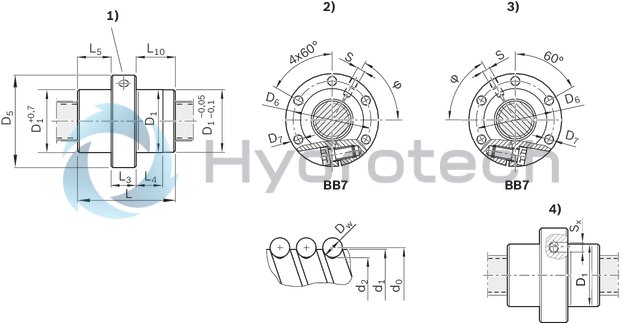
| Size D5 | 63 |
| Size L with tolerance | 57 mm |
| Bearing temperature max | |
| Series | Standard series |
| Bearing temperature min | |
| Nut or screw | Screw drive nut |
| Maximum operating temperature | |
| Footnote dynamic load capacity C | The load capacities are valid for tolerance grade T3 and T5 only. For other tolerance grades, please take into account the correction factor fac (see General Technical Notes and Information "Technical Data", Technical Notes). |
| Bearing temperature | -15 °C ... +80 °C |
| Category | B |
| Minimum operating temperature | |
| Size L4 | 18.5 |
| Size D6 | 50 |
| Size D1 f9 | 38 |
| Size D1 min | 37.945 |
| Size L3 | 20 |
| Size L10 | 18.5 |
| Size D1 max | 37.973 |
| Operating temperature | -10 °C ... +80 °C |
| Maximum permissible linear speed vmax (m/min) | 120 |
| Direction of lead | Right |
| Lead | 20 |
| Footnote static load capacity C0 | The load capacities are valid for tolerance grade T3 and T5 only. For other tolerance grades, please take into account the correction factor fac (see General Technical Notes and Information "Technical Data", Technical Notes). |
| Size L5 | 18.5 |
| Static load rating C0 | 12100 |
| Note: Maximum permissible speed vmax | See "Characteristic speed d0 • n" (section Technical notes) and "Critical speed ncr" (section Calculation and examples) |
| Nut type | SEM-E-S zero-clearance adjustable single nut |
| Productgroup ID | 17 |
| Screw drive version (drive type) | Ball screw assembly |
| Size D7 | 6.6 |
| Angle φ | 60 |
| Hole pattern | BB7 |
| Size Sx | 4 |
| Footnote permissible operating temperature (min...max) | Ball screw assemblies permit operation at continuous temperatures of up to 80 °C with temporary peaks of 100 °C, measurements taken on the outer shell of the nut in each case. |
| Dynamic load capacity C | 10900 |
| Size d1 | 19 |
| Size L | 57 |
| Size d2 | 16.7 |
| Footnote operating temperature max. | Ball screw assemblies permit operation at continuous temperatures of up to 80°C with temporary peaks of 100°C, measurements taken on the outer shell of the nut in each case. |
| Weight | 0.677 |
| Nominal size | 20 x 20R x 3,5 - 2 |
Technical data for nuts
|
Size |
C |
C0 |
vmax |
Mass |
|
d0 x P x Dw - i |
N |
N |
m/min |
kg |
| 16 x 5R x 3 - 4 | 14800 1) | 16100 1) | 30 2) | 0.24 |
| 16 x 10R x 3 - 3 | 11500 1) | 12300 1) | 60 2) | 0.25 |
| 16 x 16R x 3 - 2 | 7560 1) | 7600 1) | 96 2) | 0.42 |
| 20 x 5R x 3 - 4 | 17200 1) | 21500 1) | 30 2) | 0.31 |
| 20 x 20R x 3,5 - 2 | 10900 1) | 12100 1) | 120 2) | 0.63 |
| 25 x 5R x 3 - 4 | 19100 1) | 27200 1) | 30 2) | 0.44 |
| 25 x 10R x 3 - 4 | 18800 1) | 27000 1) | 60 2) | 0.53 |
| 25 x 25R x 3,5 - 2 | 12100 1) | 15100 1) | 150 2) | 1.13 |
| 32 x 5R x 3,5 - 4 | 25900 1) | 40000 1) | 23 2) | 0.64 |
| 32 x 10R x 3,969 - 5 | 38000 1) | 58300 1) | 47 2) | 0.87 |
| 32 x 20R x 3,969 - 2 | 16200 1) | 21800 1) | 94 2) | 1.14 |
| 32 x 32R x 3,969 - 2 | 16100 1) | 22000 1) | 150 2) | 1.44 |
| 40 x 5R x 3,5 - 5 | 34900 1) | 64100 1) | 19 2) | 0.87 |
| 40 x 10R x 6 - 4 | 60000 1) | 86400 1) | 38 2) | 1.53 |
| 40 x 20R x 6 - 3 | 45500 1) | 62800 1) | 75 2) | 1.77 |
| 40 x 40R x 6 - 2 | 30600 1) | 40300 1) | 150 2) | 3.77 |
| 50 x 5R x 3,5 - 5 | 38400 1) | 81300 1) | 15 2) | 1.23 |
| 50 x 10R x 6 - 6 | 95600 1) | 166500 1) | 30 2) | 2.44 |
| 50 x 20R x 6,5 - 3 | 57500 1) | 87900 1) | 60 2) | 3.94 |
| 50 x 40R x 6,5 - 2 | 38500 1) | 55800 1) | 120 2) | 4.42 |
| 63 x 10R x 6 - 6 | 106600 1) | 214300 1) | 24 2) | 2.94 |
| 63 x 20R x 6,5 - 3 | 63800 1) | 112100 1) | 48 2) | 4.45 |
| 63 x 40R x 6,5 - 2 | 44300 1) | 74300 1) | 95 2) | 4.95 |
| 80 x 10R x 6,5 - 6 | 130100 1) | 291700 1) | 19 2) | 4.2 |
| 80 x 20R x 12,7 - 6 | 315200 1) | 534200 1) | 30 2) | 13.3 |
| 16 x 5L x 3 - 4 | 14800 1) | 16100 1) | 0.24 | |
| 20 x 5L x 3 - 4 | 17200 1) | 21500 1) | 0.31 | |
| 25 x 5L x 3 - 4 | 19100 1) | 27200 1) | 0.44 | |
| 32 x 5L x 3,5 - 4 | 25900 1) | 40000 1) | 23 2) | 0.64 |
| 40 x 5L x 3,5 - 5 | 34900 1) | 64100 1) | 19 2) | 0.87 |
| 40 x 10L x 6 - 4 | 60000 1) | 86400 1) | 38 2) | 1.53 |
| 1) | The load ratings are valid for tolerance grades T3 and T5 only. For other tolerance grades, please take into account the correction factor fac (see General Technical Notes and Information "Technical Data", Technical Notes). |
| 2) | See "characteristic speed d0 • n" (section Technical notes) and "critical speed n"cr" (section Calculation and examples) |
Operating conditions
|
Size |
Admissible operating temperature (min ... max) 1) |
Admissible storage temperature (min ... max) |
|
d0 x P x Dw - i |
||
| 16 x 5R x 3 - 4 | -10 °C ... +80 °C | -15 °C ... +80 °C |
| 16 x 10R x 3 - 3 | ||
| 16 x 16R x 3 - 2 | ||
| 20 x 5R x 3 - 4 | ||
| 20 x 20R x 3,5 - 2 | ||
| 25 x 5R x 3 - 4 | ||
| 25 x 10R x 3 - 4 | ||
| 25 x 25R x 3,5 - 2 | ||
| 32 x 5R x 3,5 - 4 | ||
| 32 x 10R x 3,969 - 5 | ||
| 32 x 20R x 3,969 - 2 | ||
| 32 x 32R x 3,969 - 2 | ||
| 40 x 5R x 3,5 - 5 | ||
| 40 x 10R x 6 - 4 | ||
| 40 x 20R x 6 - 3 | ||
| 40 x 40R x 6 - 2 | ||
| 50 x 5R x 3,5 - 5 | ||
| 50 x 10R x 6 - 6 | ||
| 50 x 20R x 6,5 - 3 | ||
| 50 x 40R x 6,5 - 2 | ||
| 63 x 10R x 6 - 6 | ||
| 63 x 20R x 6,5 - 3 | ||
| 63 x 40R x 6,5 - 2 | ||
| 80 x 10R x 6,5 - 6 | ||
| 80 x 20R x 12,7 - 6 | ||
| 16 x 5L x 3 - 4 | ||
| 20 x 5L x 3 - 4 | ||
| 25 x 5L x 3 - 4 | ||
| 32 x 5L x 3,5 - 4 | ||
| 40 x 5L x 3,5 - 5 | ||
| 40 x 10L x 6 - 4 |
| 1) | Ball screw assemblies are suitable for continuous operation at temperatures up to 80 °C with temporary peaks of 100 °C (measurements taken on the outer shell of the nut). |
Legend
|
Symbol |
Description |
Unit |
|
d0 |
Nominal diameter |
mm |
|
P |
Lead (R = right-hand, L = left-hand) |
|
|
Dw |
Ball diameter |
mm |
|
i |
Number of ball track turns |
|
|
C |
Dynamic load capacity |
N |
|
C0 |
Static load capacity |
N |
|
vmax |
Maximum permissible speed |
m/min |
Technical notes
| 1) | Lube port at flange center (lube port machining: Flat surface L3 ≤ 15 mm, countersink L3 > 15 mm; for size 8 x 2.5 a DIN 3405 funnel-type lube nipple is provided.) |
| 2) | right |
| 3) | left |
| 4) | Nut rework: Axial lube port |
Dimensions
|
Size |
D1 min |
D1 max |
d1 |
d2 |
D1 |
D5 |
Hole pattern |
D6 |
D7 |
L |
L3 |
L4 |
L5 |
L10 |
S 1) |
Sx |
φ |
|
d0 x P x Dw - i |
f9 |
||||||||||||||||
|
mm |
mm |
mm |
mm |
mm |
mm |
mm |
mm |
mm |
mm |
mm |
mm |
mm |
mm |
mm |
° |
||
| 16 x 5R x 3 - 4 | 27.94 | 27.975 | 15 | 12.9 | 28 | 53 | BB7 | 40 | 6.6 | 38 | 15 | 10 | 11.5 | 11.5 | M6 | 4 | 53 |
| 16 x 10R x 3 - 3 | 45 | 15 | 15 | 15 | 180 | ||||||||||||
| 16 x 16R x 3 - 2 | 32.945 | 32.973 | 33 | 58 | 45 | 50 | |||||||||||
| 20 x 5R x 3 - 4 | 32.935 | 32.97 | 19 | 16.9 | 40 | 10 | 12.5 | 12.5 | 56 | ||||||||
| 20 x 20R x 3,5 - 2 | 37.945 | 37.973 | 16.7 | 38 | 63 | 50 | 57 | 20 | 18.5 | 18.5 | 18.5 | 60 | |||||
| 25 x 5R x 3 - 4 | 37.935 | 37.97 | 24 | 21.9 | 45 | 10 | 12.5 | 12.5 | |||||||||
| 25 x 10R x 3 - 4 | 64 | 16 | 22 | 22 | |||||||||||||
| 25 x 25R x 3,5 - 2 | 47.945 | 47.973 | 21.4 | 48 | 73 | 60 | 70 | 25 | 22.5 | 22.5 | 22.5 | 48 | |||||
| 32 x 5R x 3,5 - 4 | 47.935 | 47.97 | 31 | 28.4 | 48 | 20 | 10 | 14 | 14 | 60 | |||||||
| 32 x 10R x 3,969 - 5 | 27.9 | 77 | 16 | 28.5 | 28.5 | 168 | |||||||||||
| 32 x 20R x 3,969 - 2 | 55.941 | 55.969 | 56 | 80 | 68 | 64 | 22 | 22 | 22 | 60 | |||||||
| 32 x 32R x 3,969 - 2 | 88 | 34 | 34 | 34 | |||||||||||||
| 40 x 5R x 3,5 - 5 | 55.931 | 55.966 | 39 | 36.4 | 54 | 10 | 17 | 17 | M8x1 | 5 | 65 | ||||||
| 40 x 10R x 6 - 4 | 62.931 | 62.966 | 38 | 33.8 | 63 | 95 | 78 | 9 | 70 | 25 | 16 | 22.5 | 22.5 | 57 | |||
| 40 x 20R x 6 - 3 | 62.941 | 62.969 | 88 | 25 | 31.5 | 31.5 | 180 | ||||||||||
| 40 x 40R x 6 - 2 | 71.941 | 71.969 | 72 | 110 | 90 | 11 | 102 | 40 | 31 | 31 | 31 | 49 | |||||
| 50 x 5R x 3,5 - 5 | 67.931 | 67.966 | 49 | 46.4 | 68 | 98 | 82 | 9 | 54 | 25 | 10 | 14.5 | 14.5 | 67 | |||
| 50 x 10R x 6 - 6 | 71.931 | 71.966 | 48 | 43.8 | 72 | 110 | 90 | 11 | 90 | 30 | 16 | 30 | 30 | 61 | |||
| 50 x 20R x 6,5 - 3 | 84.936 | 84.964 | 43.3 | 85 | 125 | 105 | 92 | 25 | 31 | 31 | 180 | ||||||
| 50 x 40R x 6,5 - 2 | 109 | 39.5 | 39.5 | 39.5 | 60 | ||||||||||||
| 63 x 10R x 6 - 6 | 84.926 | 84.961 | 61 | 56.8 | 90 | 16 | 30 | 30 | 65 | ||||||||
| 63 x 20R x 6,5 - 3 | 94.936 | 94.964 | 56.3 | 95 | 140 | 118 | 14 | 92 | 25 | 31 | 31 | 190 | |||||
| 63 x 40R x 6,5 - 2 | 109 | 39.5 | 39.5 | 39.5 | 70 | ||||||||||||
| 80 x 10R x 6,5 - 6 | 104.926 | 104.961 | 78 | 73.3 | 105 | 150 | 125 | 95 | 16 | 32.5 | 32.5 | 67 | |||||
| 80 x 20R x 12,7 - 6 | 124.931 | 124.959 | 76 | 67 | 125 | 180 | 152 | 18 | 170 | 50 | 25 | 60 | 60 | 60 | |||
| 16 x 5L x 3 - 4 | 27.94 | 27.975 | 15 | 12.9 | 28 | 53 | 40 | 6.6 | 38 | 15 | 10 | 11.5 | 11.5 | M6 | 53 | ||
| 20 x 5L x 3 - 4 | 32.935 | 32.97 | 19 | 16.9 | 33 | 58 | 45 | 40 | 12.5 | 12.5 | 56 | ||||||
| 25 x 5L x 3 - 4 | 37.935 | 37.97 | 24 | 21.9 | 38 | 63 | 50 | 45 | 20 | 60 | |||||||
| 32 x 5L x 3,5 - 4 | 47.935 | 47.97 | 31 | 28.4 | 48 | 73 | 60 | 48 | 14 | 14 | 59 | ||||||
| 40 x 5L x 3,5 - 5 | 55.931 | 55.966 | 39 | 36.4 | 56 | 80 | 68 | 54 | 17 | 17 | M8x1 | 65 | |||||
| 40 x 10L x 6 - 4 | 62.931 | 62.966 | 38 | 33.8 | 63 | 95 | 78 | 9 | 70 | 25 | 16 | 22.5 | 22.5 | 57 |
| 1) | Lube port machining: Flat surface L3 ≤ 15 mm, countersink L3 > 15 mm; for size 8 x 2.5 a DIN 3405 funnel-type lube nipple is provided. |
Legend
|
Symbol |
Description |
|
d0 |
Nominal diameter |
|
P |
Lead (R = right-hand, L = left-hand) |
|
Dw |
Ball diameter |
|
i |
Number of ball track turns |
Attention: When setting up applications, do not allow components to collide with the front lube unit.
Nut housing MGS
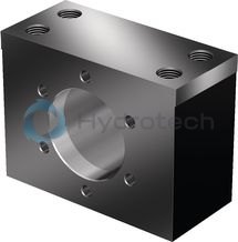
Nut housing MGS
Steel nut housings MGS are designed for FEM-E-S, FDM-E-S, FEP-E-S and SEM-E-S nuts.Catalog
Service
CAD data
Front lube unit – ball screw assembly

Front lube unit – ball screw assembly
Catalog
Service
Arrestor nut

Arrestor nut
Catalog
Service
Required and supplementary documentation
For further instructions and information, please refer to the documentation for this product.
You can find PDF files of these documents on the Internet at www.boschrexroth.com/mediadirectory.
If you are unsure about using this product, please contact Bosch Rexroth.
Notes