


BOSCH REXROTH
R151204012
$367.15 USD
- BOSCH REXROTH
- Material:R151204012
- Model:ZEM-E-S16X10RX3-3
Quantity in stock: 0
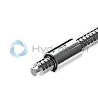
The Bosch Rexroth ZEM-E-S 16X10RX3-3 (R151204012) is a high-quality ball screw assembly designed for precise linear motion applications. This cylindrical single nut ZEMES model features a nominal diameter (d) and lead (P) with a right-hand thread direction, ensuring compatibility with various industrial requirements. The ball diameter (Dw) and the number of ball track turns (i) are engineered to provide smooth and accurate movement. Equipped with standard seals and standard axial clearance, the ZEM-E-S 16X10RX3-3 ensures durability and reliable performance in different operating environments. It has been manufactured to meet the Tolerance grade T for sizes as outlined in the product overview for screws. The nut type is categorized under the ZEMES cylindrical single nut series within the Standard series product group. This model is capable of sustaining dynamic load capacities as specified for tolerance grades T2 and T3, with a correction factor available for other tolerance grades as detailed in the general technical notes. The static load rating also adheres to these standards, ensuring that it can handle required loads without compromise. The maximum operating temperature range for this ball screw assembly is specified, allowing continuous operation at elevated temperatures with temporary peaks that can be accommodated without affecting performance. The permissible operating temperature range further underscores its robustness in varying thermal conditions. The maximum permissible linear speed (vmax) is indicated, providing users with critical information for application-specific speed requirements. Furthermore, its design permits it to maintain efficiency while supporting substantial loads, denoted by its dynamic load capacity. With a weight that complements its nominal size parameters, the Bosch Rexroth ZEM-E-S 16X10RX3-3 ball screw assembly combines strength, precision, and reliability—making it an essential component for sophisticated linear motion systems across various applications.
| Rexroth connection dimensions |
| With seals |
| With left-hand version in some cases |
| Preload class: C0, C00, C1, C2, C3 |
| Tolerance grade: T3 (for sizes as per the product overview for screws, see general technical notes and information, “Product description”), T5, T7, T9 |
| Data Sheet | Download Data Sheet |
| 3D CAD | Download 3D CAD |
| 3D CAD | Download 3D CAD |
| Manual | Download Manual |
| Manual | Download Manual |
| Manual | Download Manual |
| Manual | Download Manual |
| Manual | Download Manual |
| Size L with tolerance | 45 mm ±0,1 |
| Bearing temperature max | |
| Series | Standard series |
| Bearing temperature min | |
| Nut or screw | Screw drive nut |
| Maximum operating temperature | |
| Footnote dynamic load capacity C | The load capacities are valid for tolerance grade T3 and T5 only. For other tolerance grades, please take into account the correction factor fac (see General Technical Notes and Information "Technical Data", Technical Notes). |
| Bearing temperature | -15 °C ... +80 °C |
| Category | B |
| Size L7 | 9.5 |
| Minimum operating temperature | |
| Operating temperature | -10 °C ... +80 °C |
| Maximum permissible linear speed vmax (m/min) | 60 |
| Direction of lead | Right |
| Lead | 10 |
| Size L6 | 14.5 |
| Footnote static load capacity C0 | The load capacities are valid for tolerance grade T3 and T5 only. For other tolerance grades, please take into account the correction factor fac (see General Technical Notes and Information "Technical Data", Technical Notes). |
| Size B P9 | 5 |
| Static load rating C0 | 12300 |
| Size T1 | 3 |
| Size D1 g6 | 28 |
| Size D4 | 4 |
| Size L11 with tolerance | 16 mm +0,2 |
| Note: Maximum permissible speed vmax | See "Characteristic speed d0 • n" (see General Technical Notes and Information, "Technical Data" (Technical Notes), and "Critical speed ncr" (see General Technical Notes and Information, "Project planning notes") |
| Nut type | ZEM-E-S cylindrical single nut |
| Productgroup ID | 17 |
| Screw drive version (drive type) | Ball screw assembly |
| Size L11 | 16 |
| Footnote permissible operating temperature (min...max) | Ball screw assemblies permit operation at continuous temperatures of up to 80 °C with temporary peaks of 100 °C, measurements taken on the outer shell of the nut in each case. |
| Dynamic load capacity C | 11500 |
| Size d1 | 15 |
| Size L | 45 |
| Size d2 | 12.9 |
| Footnote operating temperature max. | Ball screw assemblies permit operation at continuous temperatures of up to 80°C with temporary peaks of 100°C, measurements taken on the outer shell of the nut in each case. |
| Weight | 0.220 |
| Nominal size | 16 x 10R x 3 - 3 |
Technical data for nuts
|
Size |
C |
C0 |
vmax |
Mass |
|
d0 x P x Dw - i |
N |
N |
m/min |
kg |
| 16 x 5R x 3 - 4 | 14800 1) | 16100 1) | 30 2) | 0.09 |
| 16 x 10R x 3 - 3 | 11500 1) | 12300 1) | 60 2) | 0.12 |
| 16 x 16R x 3 - 2 | 7560 1) | 7600 1) | 96 2) | 0.2 |
| 16 x 16R x 3 - 3 | 11200 1) | 12300 1) | 0.16 | |
| 20 x 5R x 3 - 5 | 21000 1) | 27300 1) | 30 2) | |
| 20 x 10R x 3 - 4 | 16900 1) | 21300 1) | 60 2) | |
| 20 x 20R x 3,5 - 2 | 10900 1) | 12100 1) | 120 2) | 0.34 |
| 20 x 20R x 3,5 - 3 | 16000 1) | 18800 1) | 0.37 | |
| 25 x 5R x 3 - 4 | 19100 1) | 27200 1) | 30 2) | 0.19 |
| 25 x 10R x 3 - 4 | 18800 1) | 27000 1) | 60 2) | 0.28 |
| 25 x 25R x 3,5 - 2 | 12100 1) | 15100 1) | 150 2) | 0.73 |
| 25 x 25R x 3,5 - 3 | 17600 1) | 23300 1) | 0.5 | |
| 32 x 5R x 3,5 - 4 | 25900 1) | 40000 1) | 23 2) | 0.32 |
| 32 x 10R x 3,969 - 5 | 38000 1) | 58300 1) | 47 2) | 0.5 |
| 32 x 20R x 3,969 - 2 | 16200 1) | 21800 1) | 94 2) | 0.74 |
| 32 x 20R x 3,969 - 3 | 23600 1) | 33700 1) | 0.66 | |
| 32 x 32R x 3,969 - 2 | 16100 1) | 22000 1) | 150 2) | 1.03 |
| 32 x 32R x 3,969 - 3 | 23400 1) | 34000 1) | 0.97 | |
| 40 x 5R x 3,5 - 5 | 34900 1) | 64100 1) | 19 2) | 0.44 |
| 40 x 10R x 6 - 4 | 60000 1) | 86400 1) | 38 2) | 0.88 |
| 40 x 10R x 6 - 6 | 86500 1) | 132200 1) | 1.15 | |
| 40 x 20R x 6 - 3 | 45500 1) | 62800 1) | 75 2) | 1.13 |
| 40 x 40R x 6 - 2 | 30600 1) | 40300 1) | 150 2) | 2.23 |
| 40 x 40R x 6 - 3 | 44400 1) | 62300 1) | 1.85 | |
| 50 x 5R x 3,5 - 5 | 38400 1) | 81300 1) | 15 2) | 0.62 |
| 50 x 10R x 6 - 6 | 95600 1) | 166500 1) | 30 2) | 1.34 |
| 50 x 20R x 6,5 - 3 | 57500 1) | 87900 1) | 60 2) | 2.39 |
| 63 x 10R x 6 - 6 | 106600 1) | 214300 1) | 24 2) | 1.59 |
| 80 x 10R x 6,5 - 6 | 130100 1) | 291700 1) | 19 2) | 2.23 |
| 16 x 5L x 3 - 4 | 14800 1) | 16100 1) | 30 2) | 0.09 |
| 20 x 5L x 3 - 5 | 21000 1) | 27300 1) | 0.16 | |
| 25 x 5L x 3 - 4 | 19100 1) | 27200 1) | 0.19 | |
| 32 x 5L x 3,5 - 4 | 25900 1) | 40000 1) | 23 2) | 0.32 |
| 40 x 5L x 3,5 - 5 | 34900 1) | 64100 1) | 19 2) | 0.44 |
| 40 x 10L x 6 - 4 | 60000 1) | 86400 1) | 38 2) | 0.88 |
| 1) | The load ratings are valid for tolerance grades T3 and T5 only. For other tolerance grades, please take into account the correction factor fac (see General Technical Notes and Information "Technical Data", Technical Notes). |
| 2) | See "characteristic speed d0 • n" (see General Technical Notes and Information "Technical Data" (Technical Notes), and "Critical Speed ncr" (see General Technical Notes and Information, "Project planning notes") |
Operating conditions
|
Size |
Admissible operating temperature (min ... max) 1) |
Admissible storage temperature (min ... max) |
|
d0 x P x Dw - i |
||
| 16 x 5R x 3 - 4 | -10 °C ... +80 °C | -15 °C ... +80 °C |
| 16 x 10R x 3 - 3 | ||
| 16 x 16R x 3 - 2 | ||
| 16 x 16R x 3 - 3 | ||
| 20 x 5R x 3 - 5 | ||
| 20 x 10R x 3 - 4 | ||
| 20 x 20R x 3,5 - 2 | ||
| 20 x 20R x 3,5 - 3 | ||
| 25 x 5R x 3 - 4 | ||
| 25 x 10R x 3 - 4 | ||
| 25 x 25R x 3,5 - 2 | ||
| 25 x 25R x 3,5 - 3 | ||
| 32 x 5R x 3,5 - 4 | ||
| 32 x 10R x 3,969 - 5 | ||
| 32 x 20R x 3,969 - 2 | ||
| 32 x 20R x 3,969 - 3 | ||
| 32 x 32R x 3,969 - 2 | ||
| 32 x 32R x 3,969 - 3 | ||
| 40 x 5R x 3,5 - 5 | ||
| 40 x 10R x 6 - 4 | ||
| 40 x 10R x 6 - 6 | ||
| 40 x 20R x 6 - 3 | ||
| 40 x 40R x 6 - 2 | ||
| 40 x 40R x 6 - 3 | ||
| 50 x 5R x 3,5 - 5 | ||
| 50 x 10R x 6 - 6 | ||
| 50 x 20R x 6,5 - 3 | ||
| 63 x 10R x 6 - 6 | ||
| 80 x 10R x 6,5 - 6 | ||
| 16 x 5L x 3 - 4 | ||
| 20 x 5L x 3 - 5 | ||
| 25 x 5L x 3 - 4 | ||
| 32 x 5L x 3,5 - 4 | ||
| 40 x 5L x 3,5 - 5 | ||
| 40 x 10L x 6 - 4 |
| 1) | Ball screw assemblies are suitable for continuous operation at temperatures up to 80 °C with temporary peaks of 100 °C (measurements taken on the outer shell of the nut). |
Legend
|
Symbol |
Description |
Unit |
|
d0 |
Nominal diameter |
mm |
|
P |
Lead (R = right-hand, L = left-hand) |
|
|
Dw |
Ball diameter |
mm |
|
i |
Number of ball track turns |
|
|
C |
Dynamic load capacity |
N |
|
C0 |
Static load capacity |
N |
|
vmax |
Maximum permissible speed |
m/min |
Technical notes
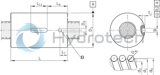
| 1) | Lube port |
Dimensions
|
Size |
d1 |
d2 |
B |
D1 |
D4 |
L |
L6 |
L7 |
L11 |
T1 |
|
P9 |
g6 |
|||||||||
|
mm |
mm |
mm |
mm |
mm |
mm |
mm |
mm |
|||
| 16 x 5R x 3 - 4 | 15 | 12.9 | 5 | 28 | 4 | 35 mm ±0.1 | 14.5 | 9.5 | 12 mm +0.2 | 3 mm +0.1 |
| 16 x 10R x 3 - 3 | 45 mm ±0.1 | 16 mm +0.2 | ||||||||
| 16 x 16R x 3 - 2 | 33 | |||||||||
| 16 x 16R x 3 - 3 | 28 | 61 mm ±0.1 | 22.5 | |||||||
| 20 x 5R x 3 - 5 | 19 | 16.9 | 33 | 45 mm ±0.1 | 14.5 | |||||
| 20 x 10R x 3 - 4 | 60 mm ±0.1 | 22 | ||||||||
| 20 x 20R x 3,5 - 2 | 16.7 | 38 | 64 mm ±0.1 | 20 mm +0.2 | ||||||
| 20 x 20R x 3,5 - 3 | 36 | 77 mm ±0.1 | 28.5 | |||||||
| 25 x 5R x 3 - 4 | 24 | 21.9 | 38 | 45 mm ±0.1 | 14.5 | 16 mm +0.2 | ||||
| 25 x 10R x 3 - 4 | 64 mm ±0.1 | 22 | 20 mm +0.2 | |||||||
| 25 x 25R x 3,5 - 2 | 21.4 | 48 | 80 mm ±0.1 | 30 | 10.5 | |||||
| 25 x 25R x 3,5 - 3 | 40 | 95 mm ±0.1 | 37.5 | |||||||
| 32 x 5R x 3,5 - 4 | 31 | 28.4 | 48 | 48 mm ±0.1 | 14 | 9.5 | ||||
| 32 x 10R x 3,969 - 5 | 27.9 | 77 mm ±0.1 | 28.5 | |||||||
| 32 x 20R x 3,969 - 2 | 56 | 64 mm ±0.1 | 22 | |||||||
| 32 x 20R x 3,969 - 3 | 50 | 84 mm ±0.1 | 32 | |||||||
| 32 x 32R x 3,969 - 2 | 56 | 88 mm ±0.1 | 34 | |||||||
| 32 x 32R x 3,969 - 3 | 50 | 120 mm ±0.1 | 50 | |||||||
| 40 x 5R x 3,5 - 5 | 39 | 36.4 | 56 | 54 mm ±0.1 | 17 | |||||
| 40 x 10R x 6 - 4 | 38 | 33.8 | 63 | 70 mm ±0.1 | 25 | 14 | ||||
| 40 x 10R x 6 - 6 | 90 mm ±0.1 | 35 | ||||||||
| 40 x 20R x 6 - 3 | 88 mm ±0.1 | 34 | ||||||||
| 40 x 40R x 6 - 2 | 72 | 113 mm ±0.1 | 46.5 | |||||||
| 40 x 40R x 6 - 3 | 63 | 142 mm ±0.1 | 61 | |||||||
| 50 x 5R x 3,5 - 5 | 49 | 46.4 | 68 | 54 mm ±0.1 | 17 | 9.5 | ||||
| 50 x 10R x 6 - 6 | 48 | 43.8 | 72 | 5 | 90 mm ±0.1 | 35 | 14 | |||
| 50 x 20R x 6,5 - 3 | 43.4 | 6 | 85 | 92 mm ±0.1 | 30 | 32 mm +0.2 | 3.5 mm +0.1 | |||
| 63 x 10R x 6 - 6 | 61 | 56.8 | 90 mm ±0.1 | 29 | ||||||
| 80 x 10R x 6,5 - 6 | 78 | 73.3 | 105 | 95 mm ±0.1 | 31.5 | 15 | ||||
| 16 x 5L x 3 - 4 | 15 | 12.9 | 5 | 28 | 4 | 35 mm ±0.1 | 14.5 | 9.5 | 12 mm +0.2 | 3 mm +0.1 |
| 20 x 5L x 3 - 5 | 19 | 16.9 | 33 | 45 mm ±0.1 | 16 mm +0.2 | |||||
| 25 x 5L x 3 - 4 | 24 | 21.9 | 38 | |||||||
| 32 x 5L x 3,5 - 4 | 31 | 28.4 | 48 | 48 mm ±0.1 | 14 | 20 mm +0.2 | ||||
| 40 x 5L x 3,5 - 5 | 39 | 36.4 | 56 | 54 mm ±0.1 | 17 | |||||
| 40 x 10L x 6 - 4 | 38 | 33.8 | 63 | 70 mm ±0.1 | 25 | 14 |
Legend
|
Symbol |
Description |
|
d0 |
Nominal diameter |
|
P |
Lead (R = right-hand, L = left-hand) |
|
Dw |
Ball diameter |
|
i |
Number of ball track turns |
Nut housing MGA
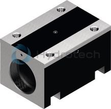
Nut housing MGA
Aluminum nut housings MGA are designed for ZEM-E-S, ZEM-E-K and ZEM-E-A nutsCatalog
Service
CAD data
Threaded Rings GWR
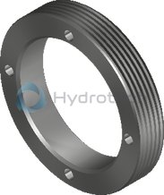
Threaded Rings GWR
For angular-contact thrust ball bearing LGNCatalog
Service
CAD data
Arrestor nut

Arrestor nut
Catalog
Service
Required and supplementary documentation
For further instructions and information, please refer to the documentation for this product.
You can find PDF files of these documents on the Internet at www.boschrexroth.com/mediadirectory.
If you are unsure about using this product, please contact Bosch Rexroth.
Notes