


BOSCH REXROTH
R150660051
$320.99 USD
- BOSCH REXROTH
- Material:R150660051
- Model:HOUSING MGD
Quantity in stock: 0
The Bosch Rexroth HOUSING (R150660051) is a meticulously engineered steel nut housing designed to complement a range of ball screw assemblies, specifically tailored for use with FEMEB, FDMEB, SEMEC, and FEDEB nuts. As part of the Productgroup ID, this particular housing exhibits a Size E classification, ensuring compatibility and optimal performance when integrated with corresponding nut sizes. The Size H specification further denotes its dimensional profile, tailored to meet precise engineering requirements. Equipped with a Hole pattern BB and Size L designation, the Bosch Rexroth HOUSING facilitates seamless installation and alignment within mechanical systems, allowing for efficient power transmission and motion control in various applications. The accessory's robust construction ensures durability and reliability in operation. The HOUSING MGD by Bosch Rexroth is recognized for its contribution to the precision and longevity of ball screw assemblies. Its role is critical in maintaining the alignment and securing the position of the ball screw nut, thus enabling smooth linear movement. This component's significance lies in its ability to withstand dynamic loads while providing a stable platform for the nut mechanism. In summary, this steel nut housing is an integral accessory that enhances the functionality of ball screw assemblies by ensuring secure fastening and precise alignment of nuts. Its specifications cater to specific sizes within the Bosch Rexroth product range, signifying its specialized application in facilitating accurate linear motion control within various mechanical setups.
Housing MGD 63x20/40
Steel nut housings MGD are designed for FEM-E-B, FDM-E-B, SEM-E-C and FED-E-B nuts, size 63x20/40
Unpacked Weight: 7.514 kg
| Steel nut housings MGD are designed for FEM-E-B, FDM-E-B, SEM-E-C and FED-E-B nuts |
| Data Sheet | Download Data Sheet |
| 3D CAD | Download 3D CAD |
| 3D CAD | Download 3D CAD |
| Manual | Download Manual |
| Manual | Download Manual |
| Manual | Download Manual |
| Manual | Download Manual |
| Manual | Download Manual |
| Size A | 100 |
| Productgroup ID | 17 |
| Size E1 | 130 |
| Size D1 h7 | 95 |
| Size N | 37 |
| Size H | 58 |
| Size E2 | 46 |
| Size D6 | 115 |
| Size S | 17 |
| Hole pattern | BB1 |
| Size T1 | 30 |
| Size T2 | 20 |
| Size L | 95 |
| Accessories for screw drives | Nut housing |
| Size B | 80 |
| Weight | 7.514 |
| Size H1 | 116 |
| Nominal size | 63x20/40 |
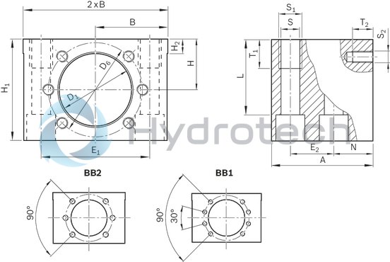
Technical data and dimensions
|
Size |
Mass |
Hole pattern |
Hex socket cap screw |
A |
B |
D1 |
D6 |
E1 |
E2 |
H |
H1 |
H2 |
N |
S |
S1 |
T1 |
S2 |
T2 |
Clamping length |
|
d0 x P x Dw |
ISO 4762 |
H7 |
L |
||||||||||||||||
|
kg |
mm |
mm |
mm |
mm |
mm |
mm |
mm |
mm |
mm |
mm |
|||||||||
|
16 x 5R/L x 3 16 x 10R x 3 16 x 16R x 3 |
0.91 | BB2 | M8 | 50 | 35 mm ±0.01 | 28 | 38 | 50 mm ±0.1 | 20 mm ±0.1 | 24 mm ±0.01 | 48 | 10 | 20 | 8.4 | M10 | 15 | M5 | 10 | 37 |
|
20 x 5R/L x 3 20 x 10R x 3 20 x 20R x 3,5 |
1.18 | 55 | 37.5 mm ±0.01 | 36 | 47 | 55 mm ±0.1 | 23 mm ±0.1 | 28 mm ±0.01 | 56 | 22 | M6 | 11 | 45 | ||||||
|
25 x 5R/L x 3 25 x 10R x 3 25 x 25R x 3,5 |
1.33 | 40 mm ±0.01 | 40 | 51 | 60 mm ±0.1 | 30 mm ±0.01 | 60 | 49 | |||||||||||
|
32 x 5R/L x 3,5 32 x 10R x 3,969 32 x 20R x 3,969 32 x 32R x 3,969 |
2.27 | M12 | 70 | 50 mm ±0.01 | 50 | 65 | 75 mm ±0.1 | 30 mm ±0.1 | 35 mm ±0.01 | 70 | 27 | 13 | M16 | 20 | M8 | 14 | 52 | ||
|
40 x 5R/L x 3,5 40 x 10R/L x 6 40 x 12R x 6 40 x 16R x 6 40 x 20R x 6 40 x 25R x 6 40 x 30R x 6 40 x 40R x 6 |
3.61 | BB1 | M14 | 80 | 60 mm ±0.01 | 63 | 78 | 90 mm ±0.1 | 35 mm ±0.1 | 42 mm ±0.01 | 84 | 12 | 31 | 15 | M18 | 25 | 17 | 65.5 | |
|
50 x 5R x 3,5 50 x 10R x 6 50 x 12R x 6 50 x 16R x 6 50 x 20R x 6,5 50 x 25R x 6,5 50 x 30R x 6,5 50 x 40R x 6,5 |
5.63 | M16 | 95 | 70 mm ±0.01 | 75 | 93 | 110 mm ±0.15 | 45 mm ±0.15 | 48 mm ±0.01 | 96 | 34 | 17 | M20 | 30 | M10 | 75 | |||
| 63 x 10R x 6 | 6.72 | 100 | 75 mm ±0.01 | 90 | 108 | 120 mm ±0.2 | 46 mm ±0.15 | 55 mm ±0.01 | 110 | 15 | 37 | 20 | 89 | ||||||
|
63 x 20R x 6,5 63 x 40R x 6,5 |
7.67 | 80 mm ±0.01 | 95 | 115 | 130 mm ±0.2 | 58 mm ±0.01 | 116 | M12 | 95 | ||||||||||
| 80 x 10R x 6,5 | 8.6 | 85 mm ±0.01 | 105 | 125 | 140 mm ±0.2 | 63 mm ±0.01 | 126 | 105 | |||||||||||
| 80 x 20R x 12,7 | 10.53 | 95 mm ±0.01 | 125 | 145 | 160 mm ±0.2 | 73 mm ±0.01 | 146 | 22 | 125 |
Legend
|
Symbol |
Description |
|
d0 |
Nominal diameter |
|
P |
Lead |
|
DW |
Ball diameter |
Attention: If a ball screw assembly with a front lube unit is used, the front lube unit may project beyond the housing. This must be considered when calculating the stroke.
In addition to bolting, the housings should be locked in place by positive means (for example, two pins with a diameter equal to that of the screws).
We recommend using screws with a strength class of 8.8.
Tightening torque
See “Installation” section “Installation in the machine”
Reference edges are formed on both sides.
Required and supplementary documentation
For further instructions and information, please refer to the documentation for this product.
You can find PDF files of these documents on the Internet at www.boschrexroth.com/mediadirectory.
If you are unsure about using this product, please contact Bosch Rexroth.