

BOSCH REXROTH
R109624085
$1,203.91 USD
- BOSCH REXROTH
- Material:R109624085
- Model:LSSDR1-40-WV-900
Quantity in stock: 0
The Bosch Rexroth LINEAR-SET LSSDR1-40-WV-900 (R109624085) is a high-precision linear motion set designed for robust and accurate linear guidance. This product consists of a precision steel shaft with a diameter of 40mm, which includes one ball guide groove for smooth and precise movements. The torqueresistant linear bushing ensures the system can handle significant torque loads without compromising performance. Crafted with hardened steel bearing plates, the LINEAR-SET LSSDR1-40-WV-900 is engineered to provide zero clearance from the factory, which enhances its stability against cocking loads. The lack of external seals in this version signifies that it’s intended for environments where additional sealing is not necessary, thus simplifying maintenance and installation. The dynamic load capacity C of this linear set indicates minimal values due to varying load directions, ensuring adaptability across different applications. It operates efficiently within a permissible ambient temperature range, maintaining performance integrity in varied working conditions. With its impressive maximum permissible linear speed (vmax) and static load rating C, this linear set can handle both dynamic and static forces effectively. Furthermore, the LINEAR-SET LSSDR1-40-WV-900 boasts a dynamic torsional moment load capacity (Mt), making it suitable for applications where rotational forces are present. Its design facilitates resistance to torsional loads while maintaining precise linear motion. This product's mass is carefully calculated to ensure optimal balance between strength and weight, contributing to its overall efficiency in application. Overall, the Bosch Rexroth LINEAR-SET LSSDR1-40-WV-900 offers reliability and precision for various industrial applications requiring accurate linear guidance without the need for additional sealing measures.
Linear set (steel), DR1-40-WV-900, without seal
Linear set (steel)
1 torque-resistant LB
Ball guide grooves = 1
Shaft diameter d = 40
Shaft included
900 = standard length as per table
Without seal
Version: Standard
Unpacked Weight: 15 kg
| Steel precision housing |
| Precision steel shaft with one ball guide groove |
| torque-resistant linear bushing |
| Torque-transmitting, hardened steel bearing plates set to zero clearance ex works |
| Stability against cocking loads |
| External seals |
| Data Sheet | Download Data Sheet |
| 2D CAD | Download 2D CAD |
| 2D CAD | Download 2D CAD |
| Manual | Download Manual |
| Manual | Download Manual |
| Manual | Download Manual |
| Manual | Download Manual |
| Manual | Download Manual |
| Series | Torque |
| Size E1 | 64 |
| Footnote dynamic load capacity C | The load capacities indicated are minimal values as the direction of loading cannot always be clearly defined. |
| Size N | 20 |
| Size H | 45 |
| Max. acceleration amax | 150 |
| Permissible ambient temperature | -10 °C ... +80 °C |
| Outer diameter D | 62 |
| Maximum permissible linear speed vmax | 3 |
| Size D | 62 |
| Mass m (kg/m) | 9.8 |
| Footnote static load capacity C0 | The load capacities indicated are minimal values as the direction of loading cannot always be clearly defined. |
| Static load rating C0 | 4350 |
| Dynamic torsional moment load capacity Mt | 53 |
| Productgroup ID | 17 |
| Standard length l of the shaft footnote | R.... ... 85: l = 900 mm, R.... ... 87: l = 1200 mm, R.... ... 88: l = 2000 mm |
| Permissible ambient temperature (max) | |
| Size E2 | 80 |
| Permissible ambient temperature (min) | |
| Size S | 13.5 |
| Shaft diameter d | 40 |
| Linear guide type | Linear bushing and shaft |
| Filter for linear bushings and shafts | Linear sets with linear bushings |
| Dynamic load capacity C | 6320 |
| Size L | 92 |
| Size B | 108 |
| Weight | 15 |
| Size D1 with tolerance | |
| Size H1 | 90 |

General technical data
|
Ø d |
mm |
12 | 16 | 20 | 25 | 30 | 40 | 50 |
|
amax |
m/s² |
150 | ||||||
|
vmax |
m/s |
3 | ||||||
|
m |
kg |
0.35 | 0.55 | 1 | 1.5 | 2.7 | 5 | 8.7 |
|
m (shaft) |
kg/m |
0.89 | 1.57 | 2.45 | 3.8 | 5.5 | 9.8 | 15.3 |
|
Operating conditions |
||||||||
|
Permissible ambient temperature (min ... max) |
-10 °C ... +80 °C | |||||||
Load capacities and load moments
|
Ød |
mm |
12 | 16 | 20 | 25 | 30 | 40 | 50 |
|
C 1) |
N |
640 | 780 | 1550 | 3030 | 3680 | 6320 | 9250 |
|
C0 1) |
N |
420 | 530 | 1050 | 2180 | 2790 | 4350 | 6470 |
|
Mt |
Nm |
2 | 3.3 | 7.5 | 15 | 23 | 53 | 103 |
| 1) | The load ratings indicated are minimal values as the load direction cannot always be clearly defined. |
| The load ratings are based on a total travel of 100, 00 m. When based on 50 000 m, the values in the table need to be multiplied by 1.26. |
Legend
|
Symbol |
Description |
Unit |
|
Ød |
Shaft diameters |
mm |
|
amax |
Maximum acceleration travel |
m/s2 |
|
C |
Dynamic load capacity |
N |
|
C0 |
Static load capacity |
N |
|
m |
Mass |
kg |
|
m (shaft) |
Weight (shaft) |
kg/m |
|
Mt |
Dynamic torsional moment load capacity |
Nm |
|
vmax |
Maximum permissible speed |
m/s |
Reduced load capacity with short stroke
In case of short stroke, the service life of the shaft is less than that of the torque-resistant Linear Bushing. The dynamic load ratings C in the tables must therefore be multiplied by the factor fs .
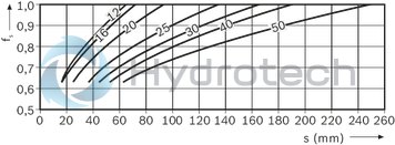
| 1) | fs = factor |
| 2) | s = movement path |
Service life, shaft straightness, stabilized installation
Definition of dynamic load ratings
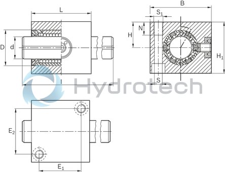
Dimensions
|
Ød |
mm |
12 | 16 | 20 | 25 | 30 | 40 | 50 |
|
D |
mm |
22 | 26 | 32 | 40 | 47 | 62 | 75 |
|
B |
mm |
42 | 50 | 60 | 74 | 84 | 108 | 130 |
|
E1 |
mm |
28 | 30 | 39 | 48 | 58 | 64 | 84 |
|
E2 |
mm |
30 | 36 | 44 | 54 | 62 | 80 | 100 |
|
H |
mm |
18 | 22 | 25 | 30 | 35 | 45 | 50 |
|
Tolerance for H 1) |
µm |
+ 13 - 22 |
||||||
|
H1 |
mm |
35 | 42 | 50 | 60 | 70 | 90 | 105 |
|
L |
mm |
40 | 44 | 55 | 68 | 80 | 92 | 114 |
|
l 2) |
mm |
400 | 500 | 600 | ||||
|
N |
mm |
12 | 15 | 18 | 20 | |||
|
S 3) |
mm |
5.3 | 6.6 | 8.4 | 10.5 | 13.5 | ||
|
S1 |
M6 | M8 | M10 | M12 | M16 | |||
| 1) | Two or more Linear Sets on one shaft are machined to the same dimension H while installed. Dimension H is reduced by 0.5 mm. |
| 2) | R.... ... 85: l = 900 mm, R.... ... 87: l = 1200 mm, R.... ... 88: l = 2000 mm |
| 3) | Fixing screws ISO 4762-8.8 |
Initial lubrication
Torque-resistant Linear Bushings do not come with initial lubrication. Grease Linear Bushings before use, see "Initial lubrication" in the "Lubrication" section.
Service life data is based on initial lubrication and relubricated Linear Bushings.
Lubricating a Linear Set with a torque-resistant compact Linear Bushing: on-shaft via Ø = 3.9 lubricating hole until lubricant seeps out. Lubricating a tandem Linear Set: on-shaft via recirculating lubricating groove in middle of outer diameter until lubricant seeps out. Lubricating a flanged Linear Set: on-shaft via funnel-type lube nipple recessed on the end face until lubricant seeps out.
Wiper seals for Torque-resistant Linear Bushings, type 1
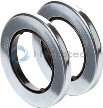
Wiper seals for Torque-resistant Linear Bushings, type 1
Galvanized metal case Elastomer wiper sealCatalog
Instructions
Service
CAD data