


BOSCH REXROTH
R108161240
$94.24 USD
- BOSCH REXROTH
- Material:R108161240
- Model:LSGF-A-12-DD
Quantity in stock: 0
The Bosch Rexroth LINEAR-SET LSGF-A-12-DD (R108161240) is a high-quality linear motion set designed for precision applications requiring smooth and accurate guidance. This model features a flanged housing made from lamellar graphite cast iron, providing robust support and durability. The set includes a super linear bushing A with a self-alignment feature, ensuring optimal performance and reducing misalignment issues. It is equipped with integrated wiper seals on both sides to protect against contaminants, enhancing the longevity of the system. The shaft diameter 'd' allows for compatibility with various design requirements, while the two retaining rings and additional spacer rings made of steel ensure secure positioning. The LINEAR-SET LSGF-A-12-DD has a standard precision class and does not allow for adjustable radial clearance, making it suitable for applications where consistent movement is critical. It does not come pre-lubricated, allowing users to apply their preferred lubrication based on specific operating conditions. With a dynamic load capacity C based on total travel of 100 km (with adjustments for travel at 50 km), this linear set can handle significant loads while maintaining smooth operation. The static load rating C0 reflects the unit's ability to withstand forces without motion. The maximum acceleration amax highlights its capability to handle rapid movements within its operating range. The permissible ambient temperature range extends from -20°C to +80°C, accommodating various environmental conditions. The breakaway force of 0.5 N signifies the minimal initial force required to initiate movement, indicating low stiction characteristics. Its maximum permissible linear speed vmax ensures that it can operate up to certain velocities without compromising service life or performance. Weighing in at 0.4 kg, this compact yet sturdy linear set is an ideal solution for vertical shaft designs in modular units within the Linear Set series, offering reliability and precision in demanding applications.
Linear set (steel), F-A-12, with two seals
Linear set (steel)
Flange
With super LB A
Shaft diameter d = 12
With two seals
Version: Standard
Unpacked Weight: 0.095 kg
This modular unit complements the Linear Set series and is used for designs with a vertical shaft.
| Precision flanged housing (lamellar graphite cast iron) |
| super linear bushing A with self-alignment feature |
| Two retaining rings with two additional spacer rings (steel) for shaft diameters 12 to 40 |
| Integrated wiper seals |
| Radial clearance not adjustable |
| No initial lubrication |
| Data Sheet | Download Data Sheet |
| 2D CAD | Download 2D CAD |
| 2D CAD | Download 2D CAD |
| 3D CAD | Download 3D CAD |
| 3D CAD | Download 3D CAD |
| Manual | Download Manual |
| Manual | Download Manual |
| Manual | Download Manual |
| Manual | Download Manual |
| Manual | Download Manual |
| Size V | 6 |
| Series | Super A (with self-alignment feature) |
| Footnote friction force FR | Frictional drags generated by linear bushings with integrated wiper seals on two sides when not under radial load. The frictional drags depend on speed and lubrication. |
| Footnote dynamic load capacity C | The dynamic load capacities are based on a total travel of 100,000 m. When based on 50,000 m, the C values in the table are to be multiplied by 1.26. |
| Max. acceleration amax | 150 |
| Permissible ambient temperature | -10 °C ... +80 °C |
| Size E | 30 |
| Size D1 with tolerance | 24 mm +0,8 |
| Outer diameter D | 22 |
| Breakaway force | 1.5 |
| Maximum permissible linear speed vmax | 3 |
| Size D | 22 |
| Size D1 | 24 |
| Footnote static load capacity C0 | The dynamic load capacities are based on a total travel of 100,000 m. When based on 50,000 m, the C values in the table are to be multiplied by 1.26. |
| Static load rating C0 | 420 |
| Size S H13 | 5.5 |
| Note: Maximum permissible speed vmax | Speeds of up to 5 m/s possible. Service life is limited by heightened wear to plastic parts. Tests have shown total travel from 50 • 105 m to 100 • 105 m without failure. |
| Friction force | 0.8 |
| Productgroup ID | 17 |
| Size W | 10 |
| Permissible ambient temperature (max) | |
| Permissible ambient temperature (min) | |
| Size L1 | 12 |
| Size D1 tolerance | |
| Shaft diameter d | 12 |
| Linear guide type | Linear bushing and shaft |
| Filter for linear bushings and shafts | Linear sets with linear bushings |
| Format of linear bushings | F – Flange |
| Dynamic load capacity C | 830 |
| Size L | 32 |
| Size D2 | 28 |
| Size B | 42 |
| Weight | 0.095 |

General technical data
|
Ø d |
mm |
12 | 16 | 20 | 25 | 30 | 40 | 50 |
|
amax |
m/s² |
150 | ||||||
|
vmax 1) |
m/s |
3 | ||||||
|
m |
kg |
0.095 | 0.16 | 0.3 | 0.57 | 1.85 | 1.65 | 3.4 |
|
FR 2) |
N |
0.8 | 1 | 1.5 | 2 | 2.5 | 3 | 4 |
|
Breakaway force |
N |
1.5 | 2 | 3 | 4.5 | 6 | 8 | 10 |
|
Shaft radial clearance h6 |
µm |
+ 38 + 10 |
+ 43 + 11 |
+ 50 + 12 |
||||
|
Operating conditions |
||||||||
|
Permissible ambient temperature (min ... max) |
-10 °C ... +80 °C | |||||||
| 1) | Speeds of up to 5 m/s possible. Service life is limited by heightened wear to plastic parts. Tests have shown total travel from 50 • 105 m to 100 • 105 m without failure. |
| 2) | Frictional drags generated by Linear Bushings with integrated wiper seals on two sides when not under radial load. The frictional drags depend on speed and lubrication. |
Load capacities and load moments
|
Ød |
mm |
12 | 16 | 20 | 25 | 30 | 40 | 50 |
|
C |
N |
830 | 1020 | 2020 | 3950 | 4800 | 8240 | 12060 |
|
C0 |
N |
420 | 530 | 1050 | 2180 | 2790 | 4350 | 6470 |
| The load ratings are based on a total travel of 100, 00 m. When based on 50 000 m, the values in the table need to be multiplied by 1.26. |
Legend
|
Symbol |
Description |
Unit |
|
Ød |
Shaft diameters |
mm |
|
amax |
Maximum acceleration travel |
m/s2 |
|
C |
Dynamic load capacity |
N |
|
C0 |
Static load capacity |
N |
|
FR |
Friction force |
N |
|
m |
Mass |
kg |
|
vmax |
Maximum permissible speed |
m/s |
Impact of load direction on load rating of closed Linear Bushings
The listed load ratings should be chosen depending on installation in minimum or maximum position and should be based on the calculations. If the load direction is clearly defined and the Linear Bushings can be installed in maximum position, the load ratings Cmax. (dynamic load rating) and C0 max (static load rating) can be used. If aligned installation is not possible or the load direction is not defined, the minimum load ratings must be used.

Reduced load capacity with short stroke
In case of short stroke, the service life of the shaft is less than that of the super Linear Bushing. The load ratings C specified in the tables must therefore be multiplied by the factor f.s .
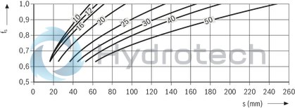
| 1) | fs = factor |
| 2) | s = movement path |
Reduced load capacity with high load
If the load F on a Super Linear Bushing A is more than F > 0.5 x C, the dynamic load rating C decreases.
Definition of dynamic load ratings
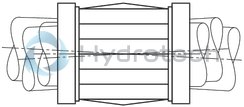
Self-alignment feature
The self-alignment feature in the steel bearing plates and machined ball guide grooves ensure quieter travel. The flow chart shows a comparison with a conventional Linear Bushing. The example is based on a load of 800 N and misalignment of about 8 ft (caused by shaft deflection).
Due to the self-alignment feature, two super Linear Bushings must be used on at least one of the shafts in the guide.
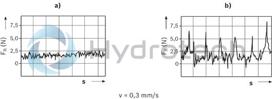
| FR = Frictional drag | |
| s = travel distance | |
| v = travel speed | |
| a) | Super Linear Bushing, A Ød 20 |
| b) | Conventional Linear Bushing, Ød 20 |
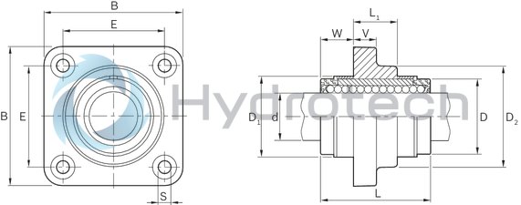
Dimensions
|
Ød |
mm |
12 | 16 | 20 | 25 | 30 | 40 | 50 | |
|
D |
mm |
22 | 26 | 32 | 40 | 47 | 62 | 75 | |
|
B 1) |
mm |
42 | 50 | 60 | 74 | 84 | 108 | 130 | |
|
D1 |
24 mm +0.8 | 28.5 mm +0.8 | 35 mm +0.8 | 43 mm +0.8 | 49.5 mm +0.8 | 66.5 mm +0.8 | 81 mm +0.8 | ||
|
D2 1) |
mm |
28 | 34 | 42 | 54 | 62 | 80 | 98 | |
|
E |
30 mm ±0.12 | 35 mm ±0.12 | 42 mm ±0.15 | 54 mm ±0.15 | 60 mm ±0.25 | 78 mm ±0.25 | 98 mm ±0.25 | ||
|
L |
mm |
32 | 36 | 45 | 58 | 68 | 80 | 100 | |
|
L1 |
mm |
12 | 15 | 18 | 23 | 26 | 36 | 72 | |
|
L1 |
12 mm | 15 mm | 18 mm | 23 mm | 26 mm | 36 mm | 72 mm | ||
|
S |
H13 |
mm |
5.5 | 6.6 | 9 | 11 | |||
|
V 1) |
mm |
6 | 8 | 10 | 12 | 14 | 16 | 18 | |
|
W |
mm |
10 | 10.5 | 13.5 | 17.5 | 21 | 22 | 14 | |
| 1) | Tolerance ISO 8062-3 - DCTG 9. |
Radial clearance
The radial clearance values shown in the table have been determined from statistics and correspond to values expected in practice. The adjustable Linear Sets come clamped to an h5 shaft (lower limit) and set to zero clearance.
Vertical dimension
The tolerance values for the vertical dimension "H" for the Linear Sets shown in the table have been determined from statistics and correspond to values expected in practice.
Bolts
We recommend bolts in accordance with ISO 4762-8.8 for fastening the Linear Sets.
Lubrication
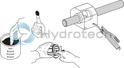
On-shaft relubrication on relubricatable Linear Bushing only until lubricant seeps out.
General mounting instructions
Wiper seals for closed-type Super Linear Bushings and Standard Linear Bushings
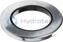
Wiper seals for closed-type Super Linear Bushings and Standard Linear Bushings
Galvanized metal case Elastomer wiper sealCatalog
Instructions
Service
CAD data
Metal cases for Super Linear Bushings and standard Linear Bushings
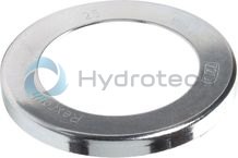
Metal cases for Super Linear Bushings and standard Linear Bushings
Galvanized steelCatalog
Instructions
Service
CAD data