

BOSCH REXROTH
R105705000
$142.53 USD
- BOSCH REXROTH
- Material:R105705000
- Model:SHAFT SUPPORT BLOC WBA-50-FO
Quantity in stock: 0
The Bosch Rexroth SHAFT SUPPORT BLOC WBA-50-FO (R105705000) is a premium quality shaft support block made from durable aluminum, designed to provide rigid shaft mounting due to its extrawide design. This model ensures top securing and features topside clamping for better accessibility, enhancing the ease of installation and maintenance. The clamping screw boasts a larger thread diameter, offering improved security when securing the shaft. This shaft support block is engineered with precision, including a reference edge that facilitates easy alignment during setup, contributing to its precise design. The inclusion of a drill hole for fastening from above, alongside the option for fastening from below, provides versatility in mounting options. This feature is particularly beneficial for quick aligning and easy installation processes. The SHAFT SUPPORT BLOC WBA-50-FO is part of Bosch Rexroth's product group of accessories for linear bushings and is compatible with linear guide types that utilize linear bushings. Its aluminum housing material not only offers robustness but also contributes to the overall lightweight nature of the component. Designed with practicality in mind, this support block negates the need for more expensive in-house designs while maintaining high standards of quality and precision. It stands as an efficient solution for various applications requiring reliable shaft support within linear motion systems.
Shaft support block (aluminum), 50-FO
Shaft support block (aluminum)
Shaft diameter d = 50
Top securing
Unpacked Weight: 1.46 kg
| Material: Aluminum |
| Rigid shaft mounting due to extra-wide design |
| Topside clamping for better accessibility |
| Better security thanks to clamping screw with larger thread diameter |
| Thread for fastening from below |
| Drill hole for fastening from above |
| Reference edge for easy alignment |
| For easy installing and quick aligning |
| Precise design with reference edge |
| More affordable than in-house designs |
| Data Sheet | Download Data Sheet |
| 2D CAD | Download 2D CAD |
| 2D CAD | Download 2D CAD |
| 3D CAD | Download 3D CAD |
| 3D CAD | Download 3D CAD |
| Manual | Download Manual |
| Manual | Download Manual |
| Manual | Download Manual |
| Manual | Download Manual |
| Manual | Download Manual |
| Manual | Download Manual |
| Manual | Download Manual |
| Manual | Download Manual |
| Manual | Download Manual |
| Manual | Download Manual |
| Size V | 12 |
| Size A | 132 |
| Productgroup ID | 17 |
| Size N2 | 42 |
| Size H | 60 |
| Size E | 100 |
| Size SW | 8 |
| Size H4 | 37 |
| Size S | 17.5 |
| Tightening torque | 120 |
| Size N1 | 49 |
| Size d H8 | 50 |
| Shaft diameter d | 50 |
| Size M | 66 |
| Linear guide type | Linear bushing and shaft |
| Accessories for linear bushings | Shaft support blocks |
| Size B | 58 |
| Housing material | Aluminum = A |
| Weight | 1.46 |
| Size D1 with tolerance | |
| Size H1 | 105 |

|
Ød |
mm |
10 | 12 | 16 | 20 | 25 | 30 | 40 | 50 | 60 |
|
m |
kg |
0.05 | 0.06 | 0.11 | 0.18 | 0.35 | 0.48 | 0.9 | 1.5 | 3 |
|
MA |
Nm |
3.8 | 6.6 | 16 | 30 | 52 | 120 | 220 | ||
Legend
|
Symbol |
Description |
Unit |
|
Ød |
Shaft diameters |
mm |
|
m |
Mass |
kg |
|
MA |
Tightening torque |
Nm |
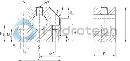
Abmessungen
|
Ød |
mm |
10 | 12 | 16 | 20 | 25 | 30 | 40 | 50 | 60 | |
|
A |
mm |
40 | 43 | 53 | 60 | 78 | 87 | 108 | 132 | 164 | |
|
B |
mm |
20 | 24 | 30 | 38 | 40 | 48 | 58 | 74 | ||
|
d |
H8 |
mm |
10 | 12 | 16 | 20 | 25 | 30 | 40 | 50 | 60 |
|
E |
27 mm ±0.15 | 30 mm ±0.15 | 38 mm ±0.15 | 42 mm ±0.15 | 56 mm ±0.15 | 64 mm ±0.15 | 82 mm ±0.15 | 100 mm ±0.2 | 124 mm ±0.2 | ||
|
H 1) |
18 mm ±0.01 | 20 mm ±0.01 | 25 mm ±0.01 | 30 mm ±0.01 | 35 mm ±0.01 | 40 mm ±0.01 | 50 mm ±0.01 | 60 mm ±0.01 | 75 mm ±0.01 | ||
|
H1 |
mm |
31 | 35 | 42 | 51 | 61 | 70 | 88 | 105 | 130 | |
|
H4 |
mm |
10 | 13 | 16 | 20 | 22 | 28 | 37 | 42 | ||
|
M 1) |
20 mm ±0.01 | 21.5 mm ±0.01 | 26.5 mm ±0.01 | 30 mm ±0.01 | 39 mm ±0.01 | 43.5 mm ±0.01 | 54 mm ±0.01 | 66 mm ±0.01 | 82 mm ±0.01 | ||
|
N1 |
mm |
14 | 16.5 | 21 | 25 | 30 | 34 | 44 | 49 | 59 | |
|
N2 |
mm |
13 | 18 | 22 | 26 | 34 | 42 | ||||
|
SW |
mm |
2.5 | 3 | 4 | 5 | 6 | 8 | 10 | |||
|
S 2) |
mm |
5.3 | 6.6 | 8.4 | 10.5 | 13.5 | 17.5 | 22 | |||
|
S1 |
M6 | M8 | M10 | M12 | M16 | M20 | M27 | ||||
|
V |
mm |
5 | 6.5 | 8 | 10 | 12 | 13 | ||||
| 1) | In relation to nominal shaft dimension "d" |
| 2) | Fixing screws ISO 4762-8.8 |